Display apparatus with reduced noise emission and driving method for display apparatus

a technology of display apparatus and noise emission, which is applied in the direction of automatic control, instruments, computing, etc., can solve the problems of affecting the stability the cost of the display apparatus, and the need for drastic measures to solve, so as to reduce the intensity of noise and avoid degradation of various characteristics

Inactive Publication Date: 2007-03-20
MAXELL HLDG LTD
View PDF26 Cites 5 Cited by
  • Summary
  • Abstract
  • Description
  • Claims
  • Application Information

AI Technical Summary

Benefits of technology

[0009]An object of the present invention is to provide a display apparatus that can reduce the intensity of noise over the entire frequency range concerned, while avoiding degradation in various characteristics.

Problems solved by technology

In these display apparatuses, the display panel is driven by a drive waveform generated in accordance with a fixed-frequency clock, and since the display panel is exposed to the outside, noise emission becomes a problem.
However, these techniques involve problems in terms of stable operation of the display apparatus and the cost of the apparatus, and drastic measures for solution are needed.
These components (noise), depending on their wavelength and strength, can cause malfunctioning or failure of other apparatuses located nearby, if this situation were left unaddressed, a valid environment for electronic apparatuses could not be provided.

Method used


Image

  • Display apparatus with reduced noise emission and driving method for display apparatus
  • Display apparatus with reduced noise emission and driving method for display apparatus
  • Display apparatus with reduced noise emission and driving method for display apparatus

Examples


first embodiment

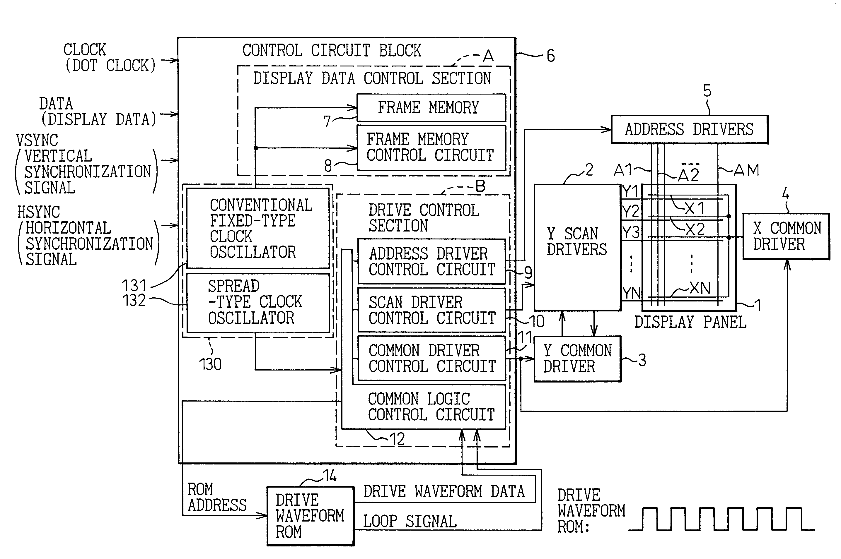
[0064]In the first embodiment, the drive control section B is supplied with the output clock of the spread-type clock oscillator 132 whose frequency varies with time within a given range centered about a set frequency, as will be described in detail later, and the address driver control circuit 9, scan driver control circuit 10, and common driver control circuit 11 operate in synchronism with the output clock of the spread-type clock oscillator 132, so that the frequency of the output waveform also varies with time. This serves to suppress the peaks of the noise emitted from various portions of the display apparatus (display panel 1), improving the noise characteristics of the apparatus as a whole.

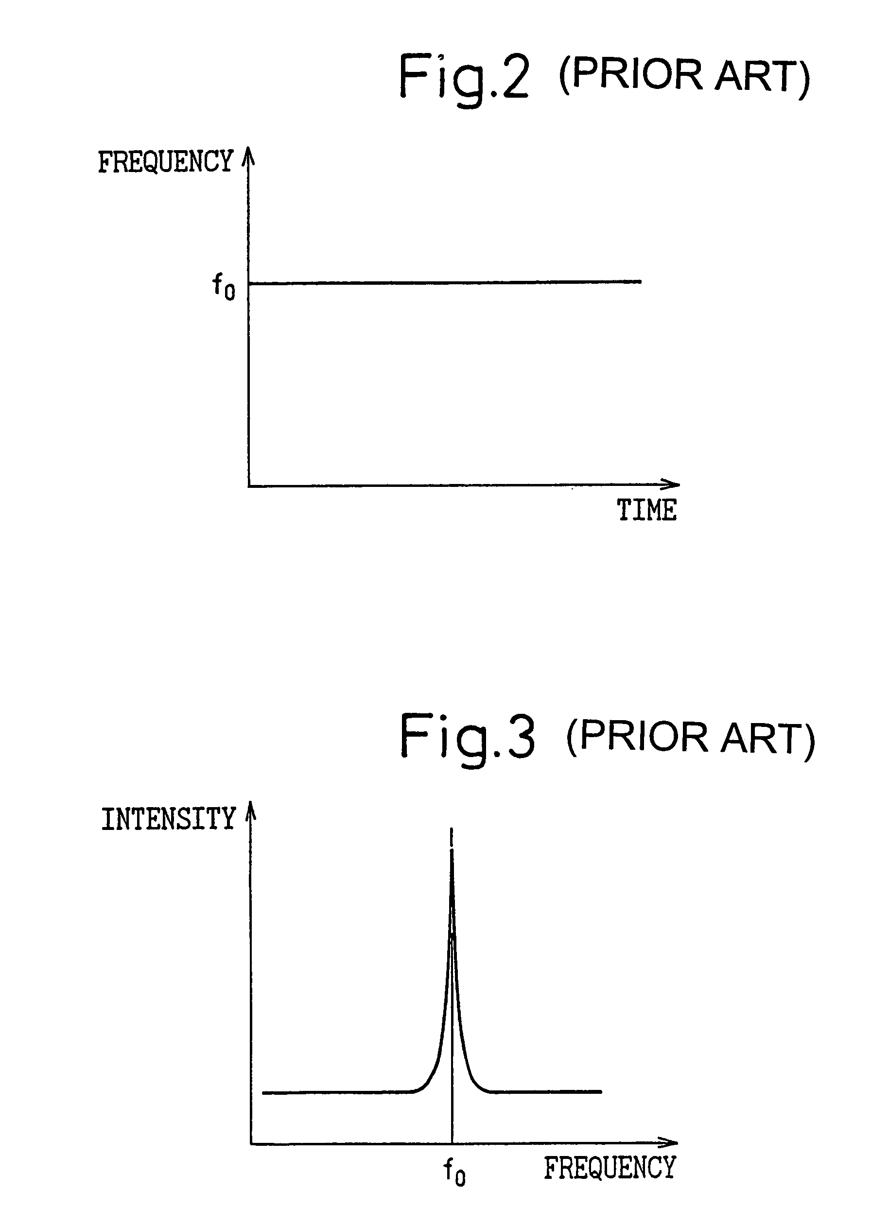
[0065]The principle of the present invention for the improvement of the noise characteristics will be described below. In the case of a fixed-frequency clock such as used in the prior art, the observed spectrum has high wavelength selectivity and exhibits very sharp peaks, but when a clock...

second embodiment

[0078]FIG. 15 is a block diagram showing a plasma display apparatus as the display apparatus according to the present invention.

[0079]As can be seen from a comparison between FIG. 15 and FIG. 7, the plasma display apparatus of the second embodiment differs from the plasma display apparatus of the first embodiment in that the clock circuit 130 in the first embodiment is replaced by a single spread-type clock oscillator 133.

[0080]That is, in the first embodiment, the output clock of the spread-type clock oscillator 132 whose frequency continuously varies with time was supplied only to the drive control section B (the common logic control circuit 12), and the output of the fixed-type clock oscillator 131 was supplied as the clock for the display data control section A (the frame memory 7 and frame memory control circuit 8); by contrast, in the second embodiment, the output clock of the spread-type clock oscillator 133 (clock circuit) whose frequency continuously varies with time is sup...

third embodiment

[0082]FIG. 16 is a block diagram showing a plasma display apparatus as the display apparatus according to the present invention.

[0083]As shown in FIG. 16, in the plasma display apparatus of the third embodiment, the clock circuit 13 is configured as a fixed-type clock oscillator as in the prior art shown in FIG. 1. In the third embodiment, however, the drive waveform ROM 140 has two banks (bank AA: 141, bank BB: 142), and control signals having different frequencies (drive waveform data and loop signal) are stored in the respective banks 141 and 142. The control signals stored in the respective banks 141 and 142 are output alternately, for example, for each frame, and the drive waveform for the display panel 1 is generated in accordance with the control signal whose frequency differs for each frame. This achieves the same effect as varying the clock frequency in an on-off fashion between two different frequencies (f+ and f−) as previously described in connection with FIGS. 13 and 14...


PUM

PropertyMeasurementUnit
frequency f0aaaaaaaaaa

Abstract

A display apparatus has a clock generating circuit, a drive waveform generating circuit, and a display panel. The drive waveform generating circuit is used to generate a drive waveform by using a clock from the clock generating circuit, and the display panel is used to display an image in accordance with the drive waveform. The clock generating circuit generates a clock whose frequency varies continuously. The drive waveform generating circuit drives the display panel by outputting a drive waveform whose frequency varies in accordance with the frequency varying clock so as to spread out noise that the display panel emits. Therefore, peak values of the noise can be reduced.

Description

BACKGROUND OF THE INVENTION[0001]1. Field of the Invention[0002]The present invention relates to a display apparatus and a method for driving the same, and more particularly to a technique for reducing noise that a display apparatus such as a plasma display panel emits.[0003]2. Description of the Related Art[0004]Recently, a variety of display apparatuses have been researched and developed, and among them, plasma display panels (PDPS) and liquid crystal displays (LCDs) have been commercially implemented as flat display apparatuses having excellent display quality.[0005]In these display apparatuses, the display panel is driven by a drive waveform generated in accordance with a fixed-frequency clock, and since the display panel is exposed to the outside, noise emission becomes a problem. To reduce noise below a specified level, it is practiced to adjust the shape of the display panel driving waveform (rise / fall shapes) or to provide a shield structure by attaching a conductive transpa...

Claims


Application Information

Patent Timeline
Patent Type & Authority Patents(United States)
IPC IPC(8): G02F1/33G09G3/296G09G3/20G09G3/288G09G3/291G09G3/298G09G5/18G09G5/36
CPCG09G3/298G09G5/18G09G2330/06G09G5/363G09G3/296
Inventor SHIBATA, HIROYUKIMURAYASU, YOSHIROWATANABE, SATOSHI
Owner MAXELL HLDG LTD
Why Eureka
Try Eureka