Optical pick-up and disc apparatus having the same

a technology applied in the field of optical pickup and disc apparatus having the same, can solve the problems of deterioration of tracking signal, difficulty in achieving the original purpose of restricting the 0th, and increase the magnitude of rf signal, so as to reduce the effect of optical transmission of noise and effective prevention of deterioration of tracking error signal due to an adjacent layer

Inactive Publication Date: 2008-08-21
SAMSUNG ELECTRONICS CO LTD
View PDF13 Cites 2 Cited by
  • Summary
  • Abstract
  • Description
  • Claims
  • Application Information

AI Technical Summary

Benefits of technology

[0020]Aspects of the present invention provide an optical pick-up in which deterioration of a tracking error signal due to an adjacent layer can be effectively prevented by decreasing an optical transmission of noise light reflected by the adjacent layer during the recording and / or the reproducing of a multilayer optical disc, and a disc apparatus having the same.
[0021]Aspects of the present invention also provide an optical pick-up in which an optical member having variable optical transmissions is provided between an objective lens and a collimating lens to relatively reduce the intensity of noise light reflected by an adjacent layer in comparison to the intensity of a signal light so that an interlayer signal coherent effect of a multilayer optical disc is effectively removed and deterioration of an RF signal characteristic is more effectively improved, and a disc apparatus having the same.
[0022]According to an aspect of the present invention, there is provided an optical pick-up to record and / or reproduce data to / from an optical disc having a plurality of recording layers, the optical pick-up including: a light source to emit a light with a wavelength corresponding to a type of the optical disc; a light collecting unit to focus the light emitted from the light source to form a light spot on a signal recording layer of the optical disc; a photodetector to receive a signal light reflected by the signal recording layer and a noise light reflected by an adjacent recording layer different from the signal recording layer, and to detect a signal from the signal light; and an optical member to change an optical transmission of the noise light according to an incident angle of the noise light so as to decrease an intensity of the noise light entering the photodetector without blocking the signal light.

Problems solved by technology

However, when, in the multilayer optical disc, the DPP method is used to detect the tracking error signal, the 0th order light reflected by the adjacent layer overlaps the ±1st order lights reflected by the reproducing layer so that the tracking signal deteriorates.
If an area of the polarized hologram is decreased in area for the purpose of decreasing the deterioration of the RF signal characteristic, it is difficult to achieve the original purpose of restricting the 0th order light (noise light) reflected by the adjacent layer from entering the sub-photodetector.
Furthermore, since the blocking area of the polarized hologram must be increased when light receiving magnification is small, the magnitude of the RF signal decreases more and the RF signal deteriorates more.
However, in this case, since signals used for the compensation (i.e., the optical signals), diffracted to the separated areas and separated from each other, contain signal coherent noise initially, it is not sufficient to help the proper compensation of the RF signal.
However, this improvement requires a greater number of components for the minute adjustment and increases manufacturing costs and manufacturing time.

Method used


Image

  • Optical pick-up and disc apparatus having the same
  • Optical pick-up and disc apparatus having the same
  • Optical pick-up and disc apparatus having the same

Examples


Embodiment Construction

[0046]Reference will now be made in detail to the present embodiments of the present invention, examples of which are illustrated in the accompanying drawings, wherein like reference numerals refer to the like elements throughout. The embodiments are described below in order to explain the present invention by referring to the figures.

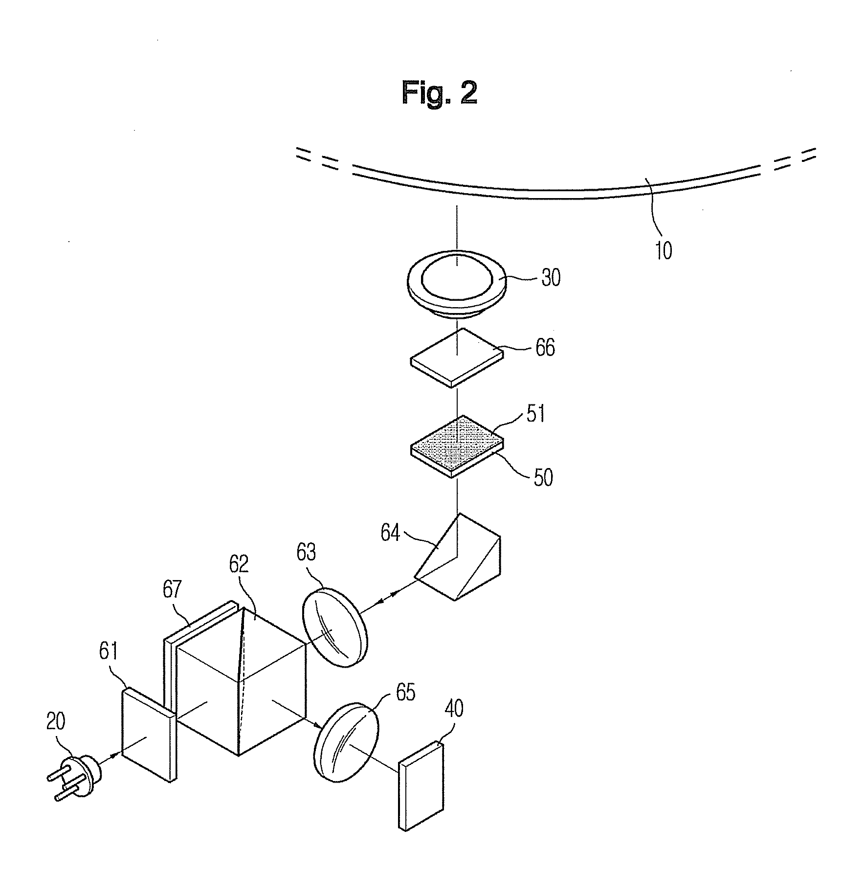
[0047]FIG. 2 is a perspective view schematically illustrating an optical system of an optical pick-up according to an embodiment of the present invention, and FIG. 3 is a plan view illustrating an arrangement of the optical pick-up illustrated in FIG. 2. The optical pick-up has an optical architecture using a light path converter and different wavelengths of light to be compatibly applied to various types of optical discs with different recording densities. The optical architecture can be configured in various ways. Generally, the optical pick-up projects a laser beam on a signal recording layer of an optical disc to record data and receives the laser ...


PUM


Abstract

An optical pick-up and a disc apparatus having the same to overcome an inferiority of a tracking signal caused by an adjacent layer during the recording and / or reproducing of an optical disc with multiple recording layers, the optical pick-up including: a light source to emit light with a wavelength corresponding to a type of the optical disc; a light collecting unit to focus the light emitted from the light source to form a light spot on a signal recording layer of an optical disc having a plurality of recording layers; a photodetector to receive a signal light reflected by the signal recording layer and a noise light reflected by an adjacent recording layer different from the signal recording layer, and to detect a signal from the signal light; and an optical member to change an optical transmission of the noise light according to an incident angle of the noise light so as to decrease an intensity of the noise light entering the photodetector.

Description

CROSS-REFERENCE TO RELATED APPLICATION[0001]This application claims the benefit of Korean Application No. 2007-16857, filed on Feb. 16, 2007 in the Korean Intellectual Property Office, the disclosure of which is incorporated herein by reference.BACKGROUND OF THE INVENTION[0002]1. Field of the Invention[0003]Aspects of the present invention relate to an optical pick-up and a disc apparatus having the same, and more particularly, to an optical pick-up in which an inferior tracking signal caused by an adjacent layer during the recording and / or reproducing of an optical disc with multiple recording layers is effectively prevented, and a disc apparatus having the same.[0004]2. Description of the Related Art[0005]With the continued evolution of image media and audio media, optical discs have been developed and commercialized to record and store high definition image information and high quality audio information for a long period of time.[0006]Such an optical disc is a recording medium on...

Claims


Application Information

Patent Timeline
IPC IPC(8): G11B7/00G11B7/135
CPCG02B5/285G02B27/0018G11B2007/0013G11B7/13922G11B7/0903G11B7/1381
Inventor KIM, BONG GI
Owner SAMSUNG ELECTRONICS CO LTD
Why Eureka
Try Eureka