Bone-conduction microphone and head-mounted Bluetooth earphone

A headphone and bluetooth headset technology, applied in earpiece/headphone accessories, etc., can solve the problems of strong correlation of voice quality, low conversion efficiency of mechanical vibration, and low sensitivity of voice signals, etc.

Active Publication Date: 2022-07-29
江西联创电声有限公司
View PDF15 Cites 0 Cited by
  • Summary
  • Abstract
  • Description
  • Claims
  • Application Information

AI Technical Summary

Problems solved by technology

However, the existing bone conduction microphones have the problems of low mechanical vibration conversion efficiency and the same sensitivity to picking up air-conducted noise a...

Method used


Image

  • Bone-conduction microphone and head-mounted Bluetooth earphone
  • Bone-conduction microphone and head-mounted Bluetooth earphone
  • Bone-conduction microphone and head-mounted Bluetooth earphone

Examples


Embodiment 1

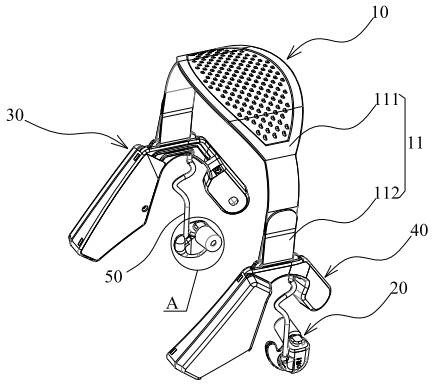
[0042] like figure 1 As shown, this embodiment provides a Bluetooth headset, including a headset 10 , two earphones 20 , a bone conduction microphone 30 , and a profiling shell 40 that is profiling with the bone conduction microphone 30 . . Wherein, the bone conduction microphone 30 and the profiling shell 40 are symmetrically arranged at the end of the headgear 10 . In specific implementation, the bone conduction microphone 30 and the profiling shell 40 are close to the cheek in front of the ear, and the purpose of symmetrical arrangement is to improve the comfort of the user wearing the Bluetooth headset. In addition, the two earphones 20 are respectively connected to the bone conduction microphone 30 and the profiling shell 40 via the wires 50 .

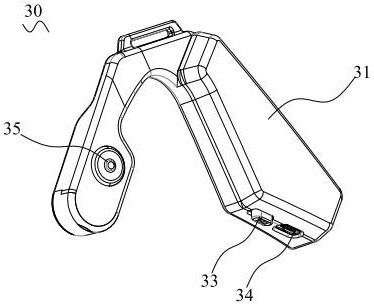
[0043] like figure 2 As shown, the bone conduction microphone 30 includes a casing 31 , a main control board (not shown) disposed in the casing 31 , a power switch 33 , an interface 34 and a button 35 embedded in the casing 31 ....

Embodiment 2

[0053] like Figure 9 As shown, the difference between this embodiment and Embodiment 1 is that the headgear 10 further includes a headgear assembly 12, and the headgear assembly 12 includes a rear bow head ring 121 that wraps the rear bow head The silicone sleeve 122 of the ring 121 and the tensile structure (not shown) which are respectively located at the two ends of the rear bow head ring 121 and are adjustable therewith; the two tensile structures are hidden in the outer shell 31 and the imitation the inner cavity of the shell 40. In this embodiment, by adding the head ring assembly 12, the rear bow head ring 121 provides an adjustment range of 15 mm with the outer shell 31 and the profiling shell 40, respectively, so that the rear bow head can be realized. The size range of the ring 121 can be adjusted to suit wearers with different head circumferences and different face shapes, and to enhance the firmness of wearing.


PUM


Abstract

The invention provides a bone conduction microphone and a head-mounted Bluetooth earphone. The bone conduction microphone comprises a shell, a surface cover and a bone conduction assembly, the surface cover is provided with a first surface and a second surface, the first surface faces the front cheek part of the ear, the first surface and the front cheek part of the ear are arranged in a clearance mode, and the second surface corresponds to the first surface; the bone conduction assembly comprises an air bag and a bone guide plate sealed at an opening of the air bag; wherein an airtight cavity defined by the air bag and the bone guide plate is filled with inert gas, and the end, away from the opening of the air bag, of the air bag penetrates through a through hole in the face cover and protrudes out of the first face till abutting against the front cheek portion of the ear, so that the air bag senses vibration of the front cheek portion of the ear; and the surface cover is used for blocking vibration of external noise sound waves to the air bag. According to the bone conduction microphone, the structure of the bone conduction microphone is optimally designed, the physical sound insulation performance of the headphone is improved to the maximum extent, the signal-to-noise ratio of the headphone is improved, and voice signals can be clearly transmitted to a receiver in a high noisy environment.

Description

technical field [0001] The invention belongs to the technical field of communication equipment, and in particular relates to a bone conduction microphone and a head-worn Bluetooth headset using the bone conduction microphone. Background technique [0002] Bone conduction technology is divided into two types: bone conduction transmission and bone conduction reception. The working mode of the bone conduction receiver is to convert the voice electrical signal into mechanical vibration for voice transmission; the working mode of the bone conduction transmitter is to convert the vibration signal into an electrical signal for voice transmission. Bone conduction speech transmission technology is widely used in bone conduction microphones. Sound waves are generated by the vibration of the vocal cords when people speak. The sound waves are not only transmitted through the air, but also transmitted to the larynx, teeth, front cheeks, forehead, and top of the head through bones and mus...

Claims


Application Information

Patent Timeline
IPC IPC(8): H04R1/10
CPCH04R1/1008H04R1/1083H04R2460/13H04R2420/07
Inventor 张俊平朱孟
Owner 江西联创电声有限公司
Why Eureka
Try Eureka