High speed modem

a high-speed modem and modem technology, applied in the field ofmodem communications, can solve the problems of inflexibility of alternatives, high cost of alternatives, and many drawbacks of analog modems

Active Publication Date: 2007-03-20
MACOM TECH SOLUTIONS HLDG INC
View PDF24 Cites 14 Cited by
  • Summary
  • Abstract
  • Description
  • Claims
  • Application Information

AI Technical Summary

Benefits of technology

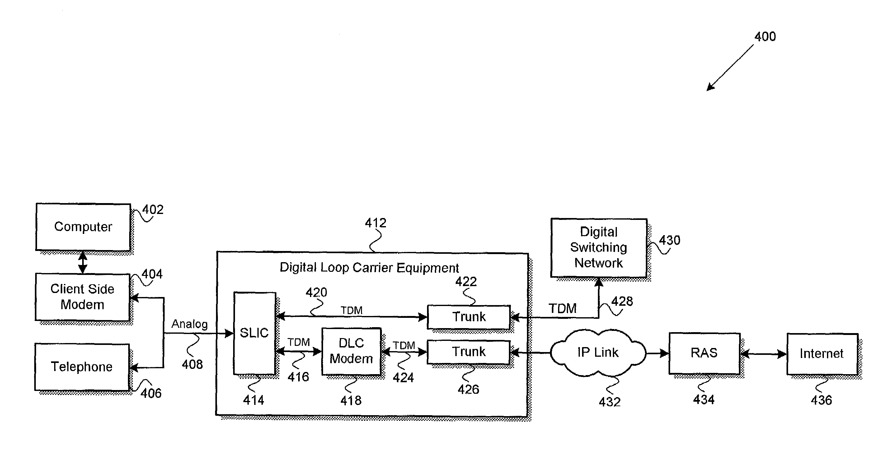
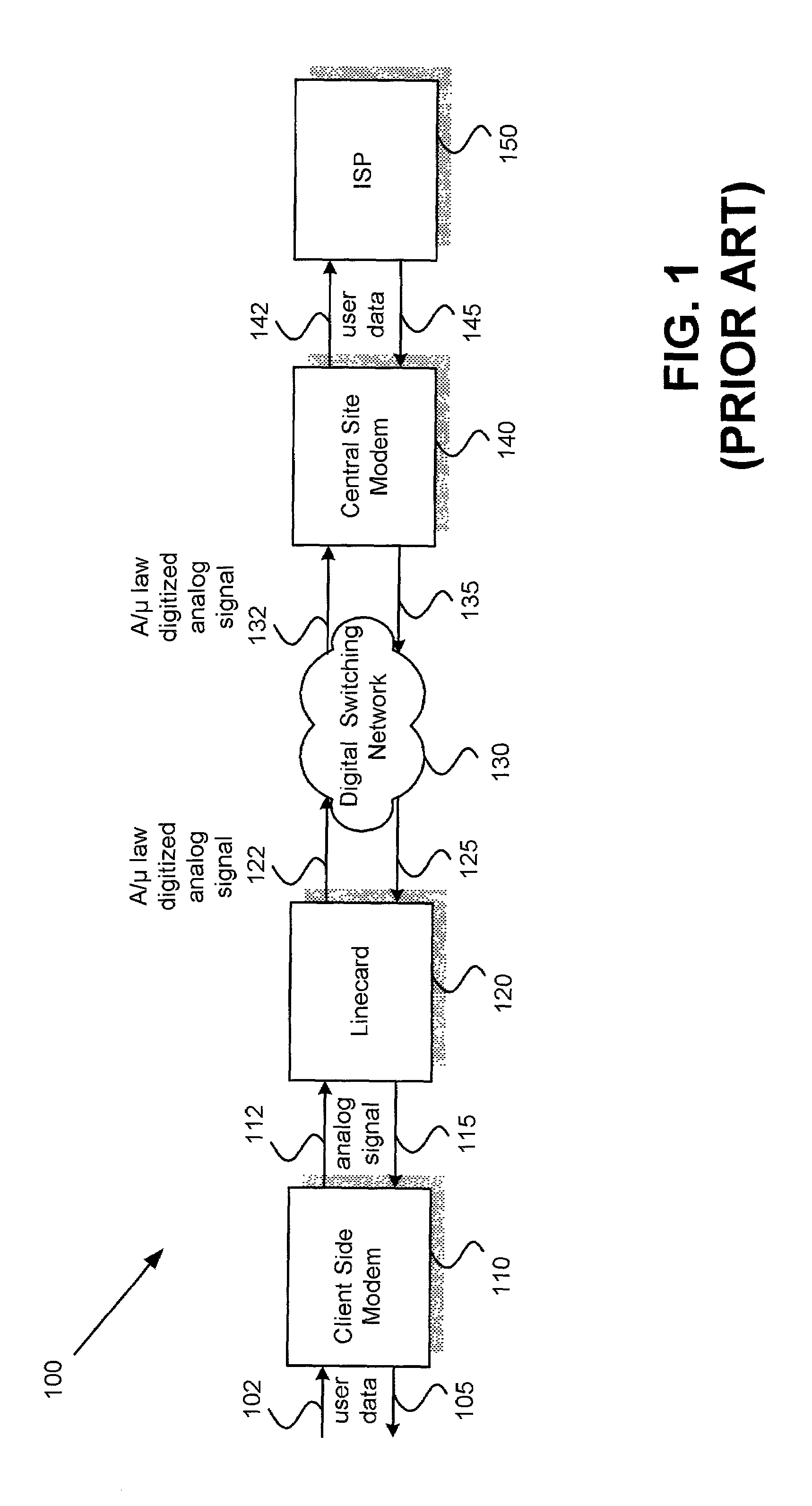
[0012]In accordance with the purpose of the present invention as broadly described herein, there is provided various high speed modem embodiments. In one aspect of the present invention, a data communication method is provided for communication over a time division multiplexed bus having one or more digital lines. The data communication method includes the step of receiving an analog data signal over a telephone line from a first modem. Subsequently, a linear coding process is employed to generate digitized analog data signal samples from the received analog data signal. For example, the linear coding process can use a sampling rate of about 16 kHz with an 8 bits / sample. Following, the digitized analog data signal samples are transmitted over one or more digital lines to a second modem, which may be a remote access server modem, for example.

Problems solved by technology

However, it is well known that such alternatives suffer from many drawbacks when compared to analog modems.
For example, (1) such alternatives are not versatile and unlike analog modems may not be simply plugged into any phone line that can support voice and all legacy voiceband modem and fax services, (2) DSL and cable services may not be available in many locations, (3) such alternatives typically require costly retrofitting at both central site and the client premises, and (4) such alternatives are considerably more expensive and take more time to be set up.
Moreover, a commercially available broadband alternative, such as DSL, also falls short of being a complete solution.
As a result, DSL service is not available on many lines that can support a substantially higher data rate than 56 kbps, but cannot support the lowest provided speeds of current DSL technology.

Method used


Image

  • High speed modem
  • High speed modem
  • High speed modem

Examples


Embodiment Construction

[0022]The present invention may be described herein in terms of functional block components and various processing steps. It should be appreciated that such functional blocks may be realized by any number of hardware components and / or software components configured to perform the specified functions. For example, the present invention may employ various integrated circuit components, e.g., memory elements, digital signal processing elements, logic elements, and the like, which may carry out a variety of functions under the control of one or more microprocessors or other control devices. Further, it should be noted that the present invention may employ any number of conventional techniques for data transmission, signaling, signal processing and conditioning, tone generation and detection and the like. Such general techniques that may be known to those skilled in the art are not described in detail herein. It should be appreciated that the particular implementations shown and describe...


PUM


Abstract

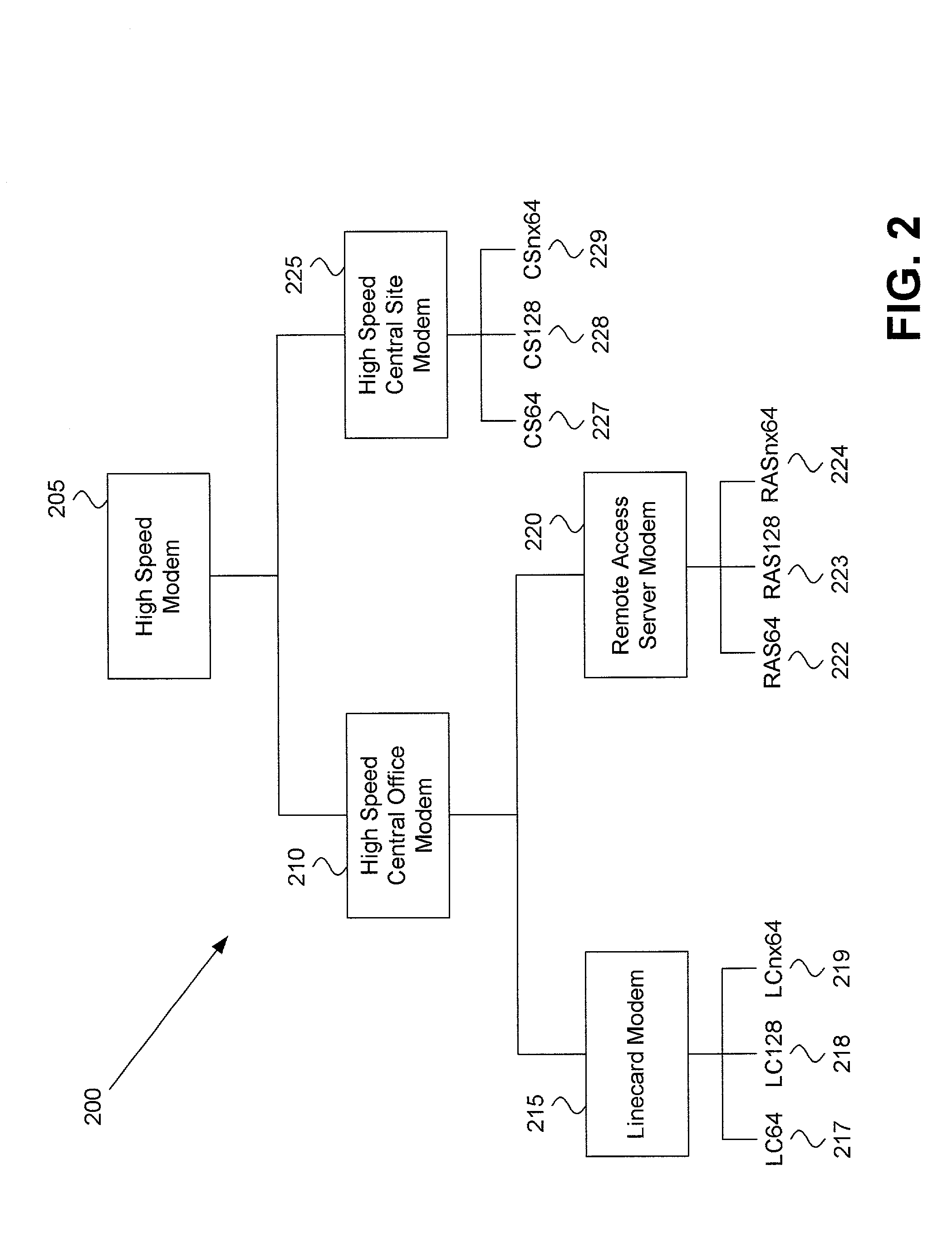
Various high speed modem embodiments are provided, for example, having a receiver configured to receive an analog data signal over a telephone line from a first modem, from which digitized analog data signal samples are generated by a processor employing a linear coding process using, for example, a sampling rate of at least 16 kHz with an 8 bits/sample. Following, the digitized analog data signal samples are transmitted over one or more digital lines of a first time division multiplexed bus to a second modem, which may be a digital loop carrier modem, for example. Thereafter, the second modem may demodulate the digitized analog data signal samples to generate digitized data, which may then be transmitted over one or more digital signal lines of a second time division multiplexed bus.

Description

RELATED APPLICATIONS[0001]The present application is a Continuation-In-Part of U.S. application Ser. No. 09 / 990,059, filed Nov. 20, 2001, and also claims the benefit of U.S. provisional application Ser. No. 60 / 322,936, filed Sep. 17, 2001. The above-referenced applications are hereby fully incorporated by reference in the present application.BACKGROUND OF THE INVENTION[0002]1. Field of the Invention[0003]The present invention generally relates to modem communications and, more particularly, to systems and methods for increasing speed and improving performance of modems.[0004]2. Related Art[0005]As the popularity of the Internet continues to increase, consumers and Internet Service Providers (ISPs) seek new methods and systems for providing data at a higher throughput in a way that requires minimal expense and retrofitting at the subscriber's premises. The need for transferring data at higher rates has been intensifying day by day due to the increased use of the Internet to transfer ...

Claims


Application Information

Patent Timeline
Patent Type & Authority Patents(United States)
IPC IPC(8): H04L12/66H04L5/16H04L12/64H04Q11/04
CPCH04Q11/04H04L2012/6424H04L2012/6427H04L2012/6481H04Q2213/13299H04Q2213/13034H04Q2213/13199
Inventor BEADLE, MICHAEL S.METZGER, MICHAEL M.BRENT, JASON B.
Owner MACOM TECH SOLUTIONS HLDG INC
Why Eureka
Try Eureka