Image recording device

a recording device and image technology, applied in the field of image recording devices, can solve the problems of image quality deterioration and image quality conspicuous, and achieve the effects of enhancing the s/n ratio, and enhancing the correlative level of the respective fram

Active Publication Date: 2007-03-20
MAXELL HLDG LTD
View PDF14 Cites 6 Cited by
  • Summary
  • Abstract
  • Description
  • Claims
  • Application Information

AI Technical Summary

Benefits of technology

[0010]The above recursive noise reduction circuit performs the leveling-out of the frames in the time axis direction through the recursion of the differential signal to the non-compressed digitalized images signals input. The noises are of poor correlation so that during the leveling-out operation of the frames they are counterbalanced in the time axis direction thereof and reduced so as to improve the S / N ratio. On the other hand, during such operation, the correlation between the anterior and posterior frames of the images signals is high so as to enhance the correlative level of the respective frames without sacrificing the images signals. The enhancement of the correlative level of the respective frames leads to the reduction of the digital value of the non-compressed data so as to allow for the lower compressibility thereof, by the compression recording means. The higher the feedback gain in recursion is, the more the leveling-out of the frames is intensified so as to further improve the S / N ratio and to enhance the correlative level between the frames. There is tendency that the higher the compressibility thereof is, the further the image quality is deteriorated owing to the block and mosquito noises and as such. The deterioration of the image quality becomes conspicuous when the compressibility thereof goes beyond a given level. The controlling of the feedback gain and the filter characteristic in the recursive noise reduction circuit according to the correlation between the compressibility of the digitalized images signals and the block and mosquito noises allows the correlative level between the frames of non-compressed signals to change, which leads to a more efficient compression. Such efficient compression results in the restraint of the increased compressibility thereof and in the reduction of the digital value of the non-compressed signals due to the noise reduction effect.

Problems solved by technology

There is tendency that the higher the compressibility thereof is, the further the image quality is deteriorated owing to the block and mosquito noises and as such.
The deterioration of the image quality becomes conspicuous when the compressibility thereof goes beyond a given level.

Method used


Image

  • Image recording device
  • Image recording device
  • Image recording device

Examples


first embodiment

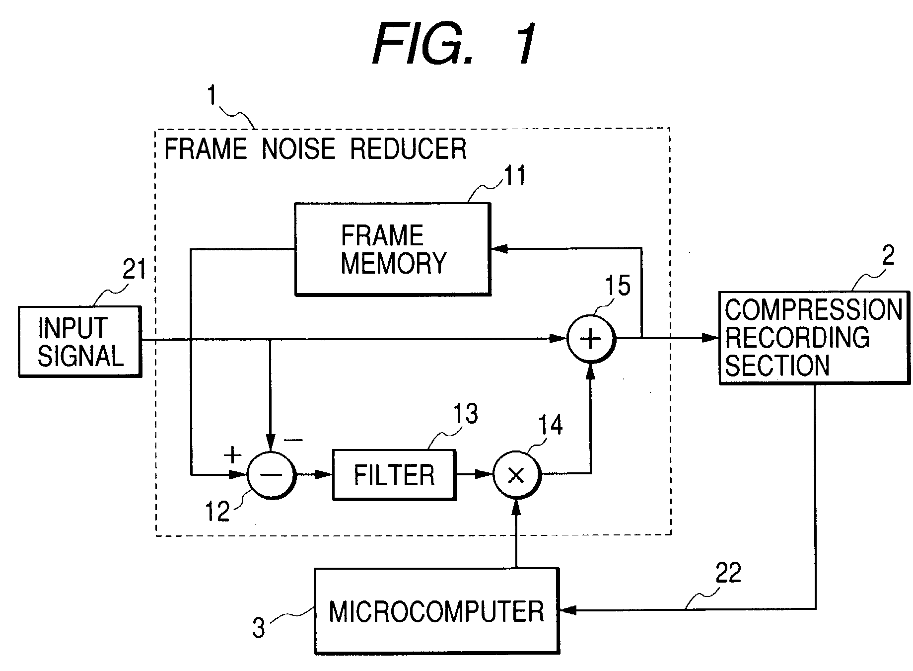
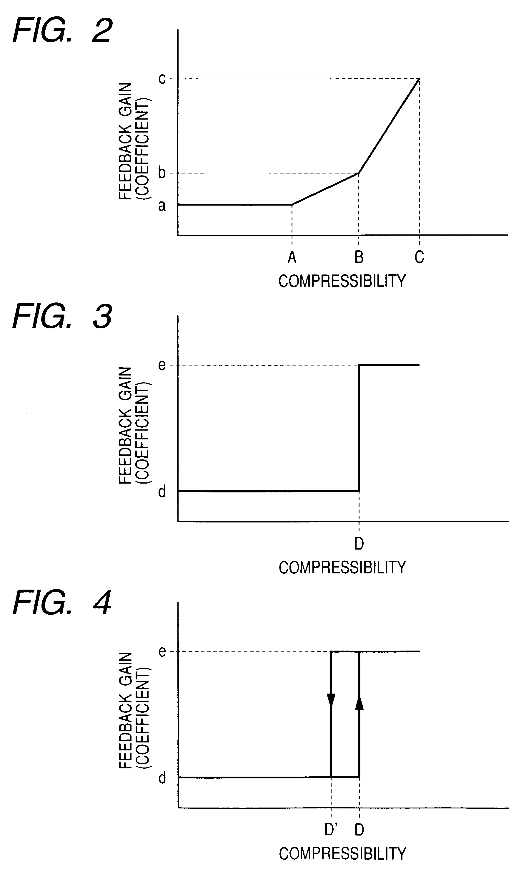
[0019]FIGS. 1 through 4 are explanatory views of the invention. FIG. 1 is a block diagram of an image recording device of the instant embodiment. FIGS. 2 through 4 are the first, second and third characteristics respectively of the control means as shown in FIG. 1.

[0020]The first embodiment of the invention is an example when the feedback gain is controlled in response to the compressibility of the digitalized images signals by means of the control means.

[0021]Reference numerals in FIG. 1 respectively indicate, 1 a frame noise reducer functioning as a so-called recursive noise reduction circuit, 2 a compression recording section functioning as a means to compress and record the digitalized images signals, 3 a microcomputer as the control means, 11 a frame memory to memorize the digitalized images signals, 12 a differential signal generation circuit as a means to generate a signal arranged with the difference (hereinafter, referred to as a differential signal) between the adjoining f...

second embodiment

[0026]FIGS. 5 and 6 are explanatory views of the invention. FIG. 5 is a block diagram of an image recording device, and FIG. 6 shows the controlling characteristic of the control means of FIG. 5.

[0027]The second embodiment is an example when the filtering characteristic of the recursive noise reduction circuit is checked by the control means according to the compressibility of the signals.

[0028]In FIG. 5, reference numeral 3′ indicates a microcomputer adopted for the control means. The microcomputer 3′ detects a compressibility signal 22 from the compression recording section 2 and checks the filtering characteristic of a filter 13 incorporated in the frame noise reducer 1 adopted for the recursive noise reduction circuit. The differential signal output from the differential signal generation circuit 12 adopted for the differential signal generation means is input to the filter 13, which filter performs the filtering operation on the differential signal in response to the correlativ...

third embodiment

[0032]FIG. 7 is an explanatory view of the invention.

[0033]The instant embodiment is arranged so that the feedback gain (or coefficient) generated at the feedback gain generation means of the recursive noise reduction circuit and the filtering characteristic of the filter thereof are alternatively or simultaneously controllable by means of the control means in response to the compressibility of the input signal.

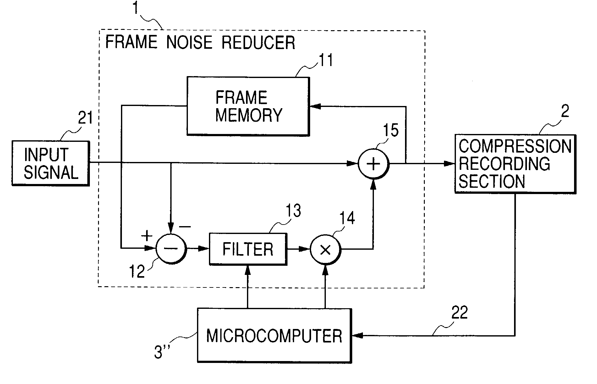
[0034]In FIG. 7, reference numeral 3″ indicates a microcomputer adopted for the control means. The microcomputer 3″ detects a compressibility signal 22 from a compression recording section 2 and accordingly controls the feedback gain (or coefficient) generated at the circuit 14 of the frame noise reducer 1 adopted as the recursive noise reduction circuit and the filtering characteristic of the filter 13 thereof.

[0035]The arrangement and operation for controlling the feedback gain (or coefficient) are the same as described in the first embodiment, and those for controlling the...


PUM


Abstract

An image recording device that compresses and records image data is provided wherein noise reduction is recursively performed on the non-compressed image signals and the feedback gain or the filtering characteristic of a recursive noise reduction circuit are controlled according to the compressibility of the image data in order to reduce the compressibility of the non-compressed image signals without deterioration or to improve the compressibility efficiency thereof and to reduce the digital value of the compressed image data with the frame noises in restraint.

Description

BACKGROUND OF THE INVENTION[0001]1. Technical Field of the Invention[0002]The present invention relates to an image recording device that compresses and records the digitalized image signals.[0003]2. Description of the Related Art[0004]The digital value of the compressed data of the prior image recording device is normally restricted, which device digitalizes images and subjects the same images to compression coding for recording. For instance, as for a DVD-RAM recorder, the bit rate thereof is defined according to the recording speed, volume and the maximum recording time of the medium in use, which requires the digital value of the compressed images data to be restricted to a given value or below. Thus, when the digital value of the images data prior to compression is large such as high-precise and complicated images and the same value of the compressed images data goes beyond the definitive bit rate, it is controlled such that the compressibility of the subject data is enhanced s...

Claims


Application Information

Patent Timeline
Patent Type & Authority Patents(United States)
IPC IPC(8): G06K9/36G06K9/46H04N5/21G06K9/40G06T5/00H04N5/92H04N19/00H04N19/102H04N19/117H04N19/146H04N19/80H04N19/85H04N19/86
CPCG06T5/002G06T5/50H04N19/154H04N19/152H04N19/117
Inventor SATOU, KAZUYUKINAKANO, TAKAHIROAKUTSU, HAJIME
Owner MAXELL HLDG LTD
Why Eureka
Try Eureka