Optical transmission apparatus and optical systems

Inactive Publication Date: 2007-03-20
HITACHI LTD
View PDF22 Cites 0 Cited by
  • Summary
  • Abstract
  • Description
  • Claims
  • Application Information

AI Technical Summary

Benefits of technology

[0007]An object is, in accordance with the present invention, for dissolving the drawbacks in the conventional related arts mentioned in the above, to provide an optical transmiss

Problems solved by technology

The optical transmission apparatus in accordance with the related prior art must have at least two kinds of light sources, therefore, it has drawback

Method used


Image

  • Optical transmission apparatus and optical systems
  • Optical transmission apparatus and optical systems
  • Optical transmission apparatus and optical systems

Examples


Example

[0037]Hereinafter, detailed explanation of the embodiments of an optical transmission apparatus, an optical repeater including the optical transmission apparatus, and an optical network using the optical repeater(s), in accordance with the present invention, will be given by referring to attached drawings.

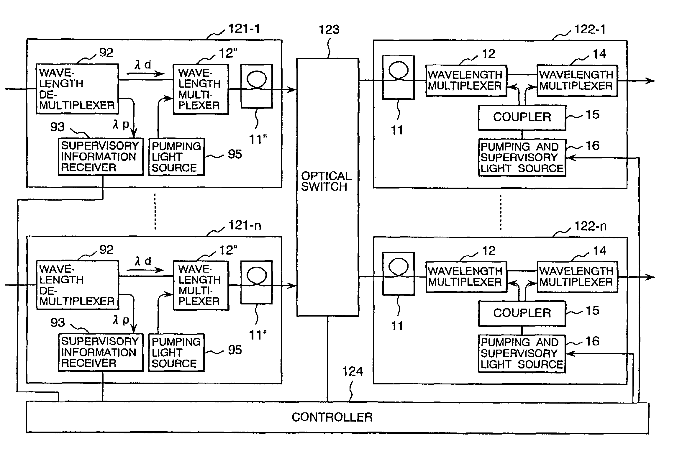
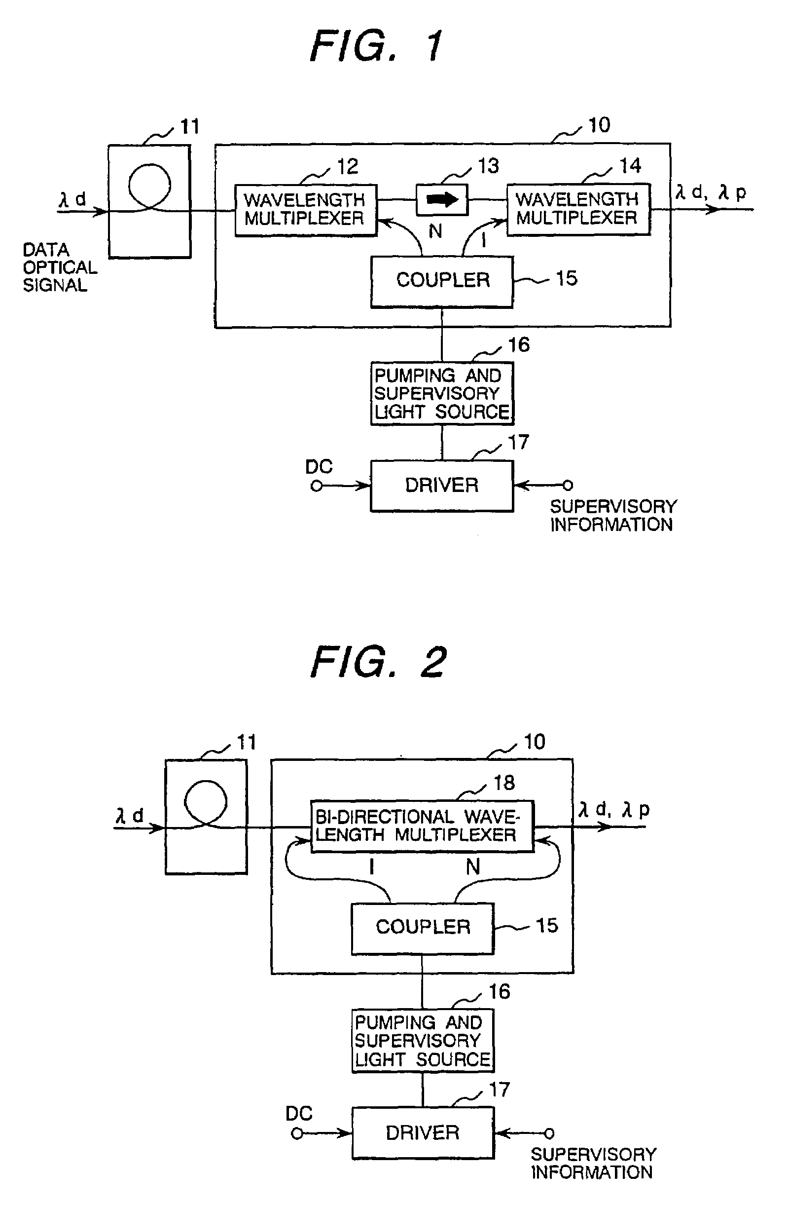
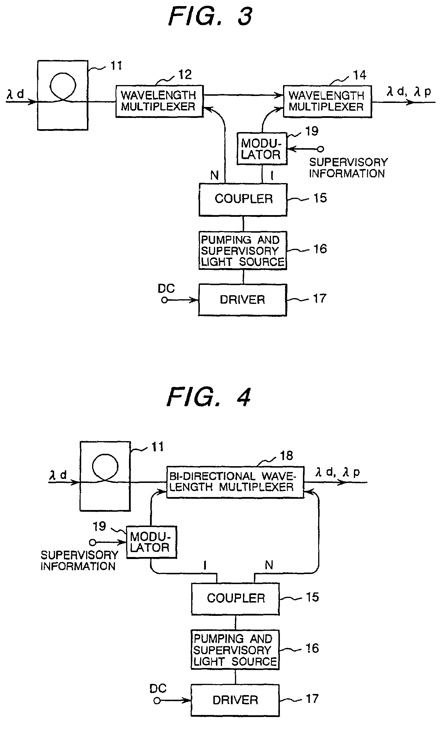
[0038]FIG. 1 is a block diagram of showing basic structure of the optical transmission apparatus in accordance with an embodiment of the present invention; and FIG. 2 is a block diagram of showing another basic structure of the optical transmission apparatus in accordance with another embodiment of the present invention. In FIGS. 1 and 2, a reference numeral 11 denotes a doped fiber which is doped with Erbium, etc., 12 and 14 wavelength multiplexers, 13 an isolator, 15 an optical coupler, 16 a pumping and supervisory light source, 17 a driver, 18 a bi-directional wavelength multiplexer. In those FIGS. 1 and 2, however, the optical transmission apparatus in accordance with the embod...


PUM


Abstract

An optical transmission apparatus, an optical repeater using the optical transmission apparatus, and an optical cross-connect equipment for controlling switches depending on supervisory information, comprising: a doped fiber for amplifying an optical signal of wavelength οd; a wavelength multiplexer for outputting a pumping light to the doped fiber; a wavelength multiplexer for multiplexing an amplified optical signal and a supervisory optical signal to as to output it to an optical fiber at downstream side; a pumping and supervisory light source; an optical coupler for distributing the light from the light source at a ratio of N:1 to the wavelength multiplexers; and a driver for controlling the light source by adding the supervisory information and a direct current signal.

Description

RELATED APPLICATIONS[0001]This application is related to and claims priority to U.S. patent application Ser. No. 10 / 172,811 entitled “OPTICAL TRANSMISSION APPARATUS AND OPTICAL SYSTEM” filed Jun. 14, 2002, which in turn claims the benefit of priority from U.S. Pat. No. 6,424,445, issued on Jul. 23, 2002, which also maintains the benefit of priority from Japanese Patent Application No. 9-04099, filed on Feb. 25, 1997, the entirety of which are incorporated herein by reference.BACKGROUND OF THE INVENTION[0002]1. Field of the Invention[0003]The present invention relates to an optical transmission apparatus, an optical repeater and an optical cross-connect equipment, and in particular, relates to an optical transmission apparatus, an optical repeater and an optical cross-connect equipment, each having an optical amplifier by means of an optical fiber doped with Erbium, etc., therein.[0004]2. Description of Related Art[0005]In a network constructed by connecting a plurality of node equip...

Claims


Application Information

Patent Timeline
IPC IPC(8): H04B10/08H04B10/00H04J14/00H04J14/02H01S3/13H01S3/131H04B10/073H04Q11/00
CPCH01S3/1301H04B10/0731H04Q11/0001H04Q11/0005H04Q11/0062H01S3/10015H04Q2011/0039H04Q2011/0049H04Q2011/0069H04Q2011/0083H01S3/0078H01S3/06754H01S3/2391H01S3/13013
Inventor TSUSHIMA, HIDEAKIKITAJIMA, SHIGEKISAWADA, YASUSHI
Owner HITACHI LTD
Why Eureka
Try Eureka