Bicycle shift operating device

a technology of operating device and bicycle, which is applied in the direction of mechanical control device, cycle equipment, instruments, etc., can solve the problems of requiring uncomfortable or unnatural movements of the rider's hands to operate, prior shifting device can be complicated and expensive to manufacture and assemble, and can be difficult to operate. to achieve the effect of convenient operation

Inactive Publication Date: 2007-03-27
SHIMANO INC
View PDF24 Cites 29 Cited by
  • Summary
  • Abstract
  • Description
  • Claims
  • Application Information

AI Technical Summary

Benefits of technology

[0007]One object of the present invention is to provide a bicycle shift operating device with a pair of operating (shifting) levers that are easily to operate.
[0009]Another object of the present invention is to provide a bicycle shift operating device that is relatively simple and inexpensive to manufacture and assemble.
[0010]Still another object of the present invention is to provide a bicycle shift operating device that provides reliable shifts of the front and rear derailleurs.

Problems solved by technology

These prior shifting devices can require uncomfortable or unnatural movements of the rider's hands to operate.
Furthermore, some of these prior shifting devices are sometimes cumbersome to operate because the levers are pivoted in opposite directions or require a significantly different shifting motion to operate each of the levers.
Moreover, some of these prior shifting devices can be complicated and expensive to manufacture and assemble.

Method used


Image

  • Bicycle shift operating device
  • Bicycle shift operating device
  • Bicycle shift operating device

Examples


second embodiment

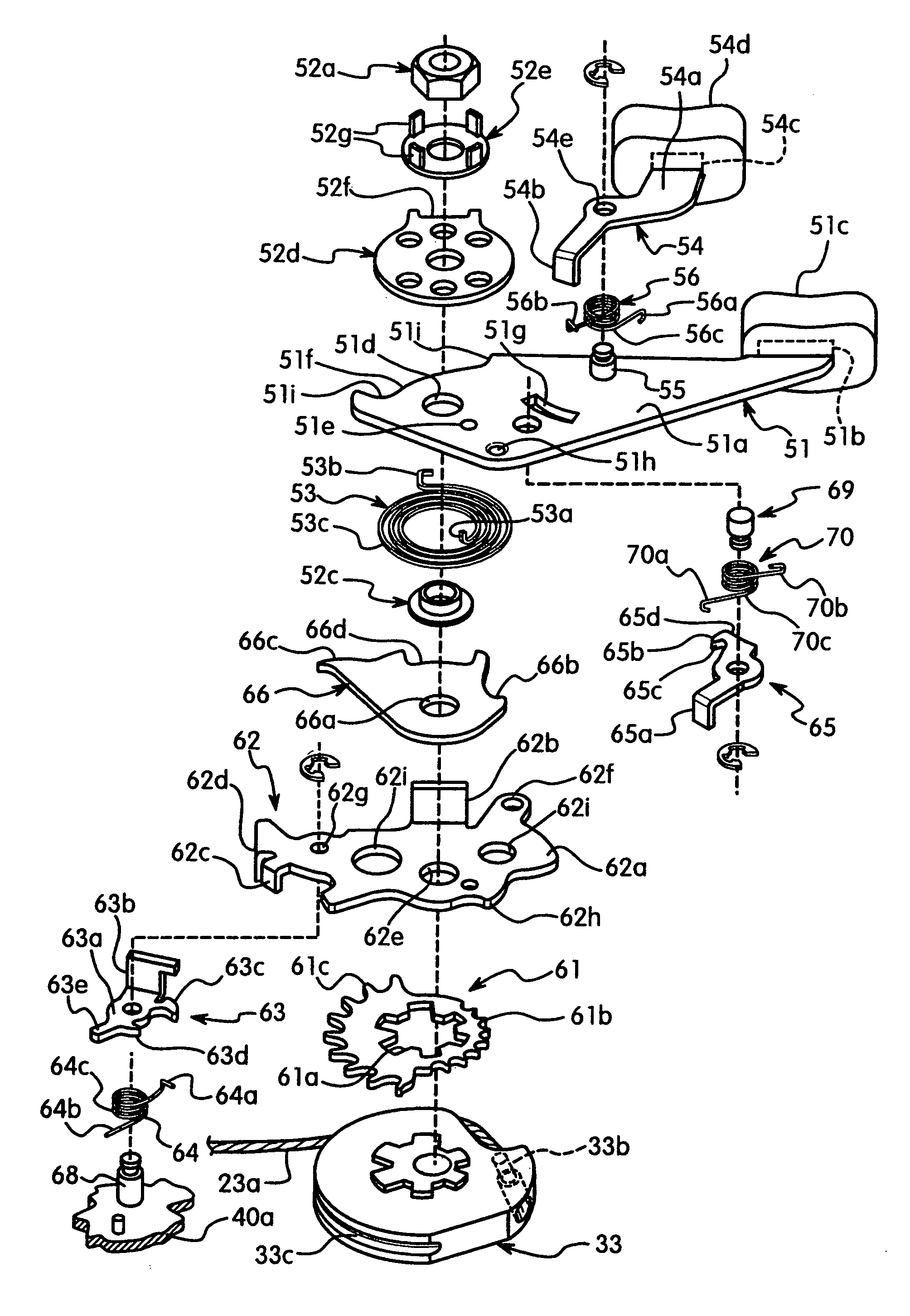
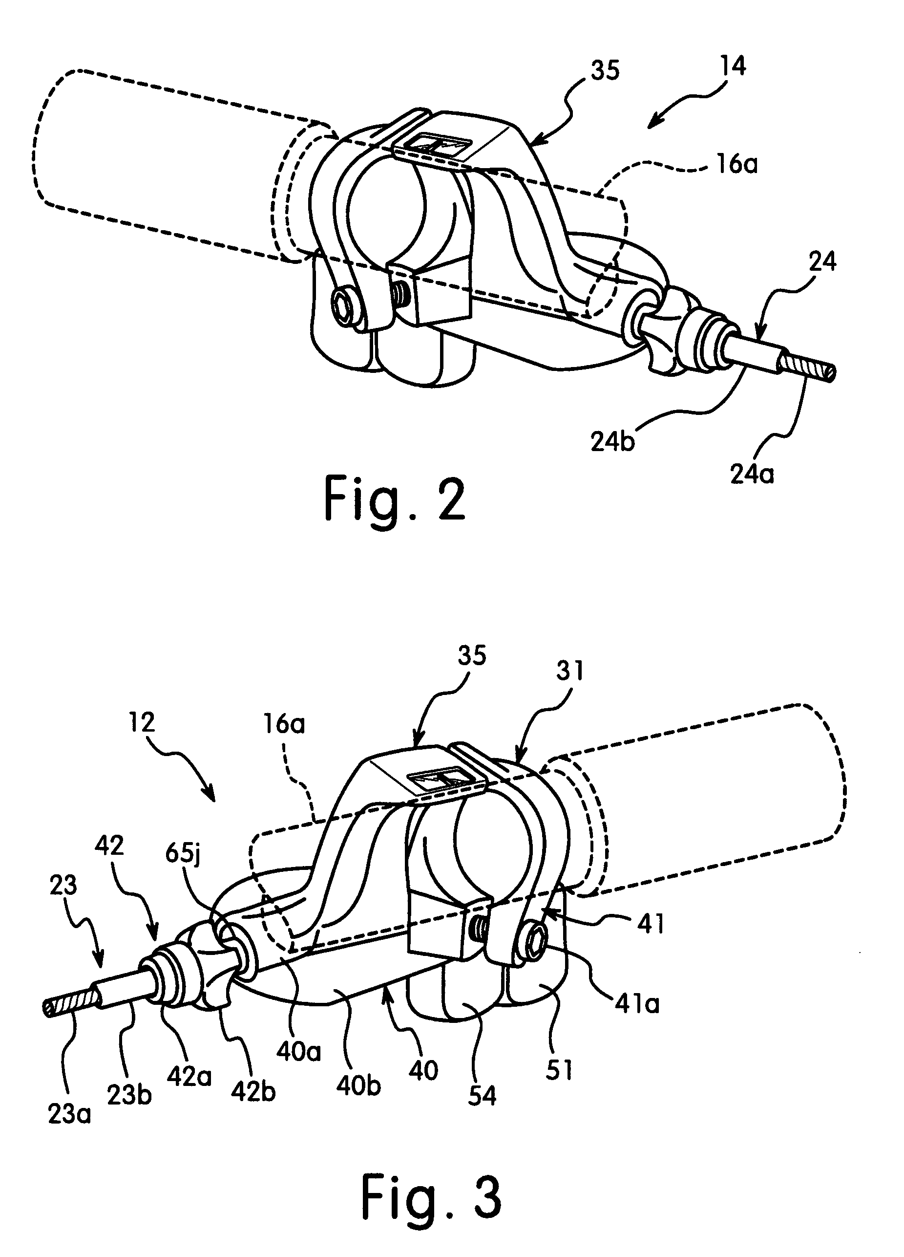
[0107]Referring now to FIG. 40, a front or left shift operating device 112 in accordance with a second embodiment will now be explained. Basically, the shift operating device 112 is identical to the shift operating device 12, except that the present invention has been adapted to a drop type of a handlebar 116a and the winding ratchet member has fewer teeth. In other words, the internal mechanism of the shift operating device 112 is identical to the shift operating device 12, except that the present invention has been adapted to the drop type handlebar 116a and fewer teeth are used in the winding ratchet member. In view of the similarity between the first and second embodiments, the descriptions of the parts of this second embodiment have been omitted for the sake of brevity.

[0108]The operating mechanism of this embodiment basically includes a first operating (pulling lever) member 151 mounted on a main axle and a second operating (releasing lever) member 154 pivotally mounted on a s...


PUM


Abstract

A bicycle shift operating device is basically provided with a first operating member, a second operating member, a shift wire take-up element and a wire winding / release mechanism. The second operating member is operatively coupled to the first operating member to move with the first operating member during movement of the first operating member, and to move the first operating member during movement of the second operating member. The shift wire take-up element is rotated in a first rotational direction by the first operating member and in a second rotational direction that is opposite to the first rotational direction by the second operating member. The wire winding / release mechanism is operatively coupled to the shift wire take-up element and the first and second operating members to selectively hold the shift wire take-up element in one of a plurality of shift positions.

Description

BACKGROUND OF THE INVENTION[0001]1. Field of the Invention[0002]This invention generally relates to a bicycle shift operating device. More specifically, the present invention relates to a shift operating device having a pair of operating (shifting) levers that are moved in substantially the same rotational direction.[0003]2. Background Information[0004]Bicycling is becoming an increasingly more popular form of recreation as well as a means of transportation. Moreover, bicycling has become a very popular competitive sport for both amateurs and professionals. Whether the bicycle is used for recreation, transportation or competition, the bicycle industry is constantly improving the various components of the bicycle. One part of the bicycle that has been extensively redesigned is the bicycle transmission. Specifically, a bicycle transmission typically includes front and rear shifting mechanisms or shift operating devices that operate front and rear derailleurs to move a chain laterally ...

Claims


Application Information

Patent Timeline
Patent Type & Authority Patents(United States)
IPC IPC(8): G05G11/00B62M25/02B62M25/04
CPCB62M25/04Y10T74/20043Y10T74/2014Y10T74/20287Y10T74/2042Y10T74/20438
Inventor KAWAKAMI, TATSUYA
Owner SHIMANO INC
Why Eureka
Try Eureka