Circulating fluidized bed boiler

a fluidized bed and boiler technology, applied in the direction of fluidized bed heat exchangers, combustion processes, lighting and heating apparatus, etc., can solve the problem of inability to control the operation of heat exchangers

Inactive Publication Date: 2007-03-27
KVAERNER POWER OY
View PDF16 Cites 22 Cited by
  • Summary
  • Abstract
  • Description
  • Claims
  • Application Information

AI Technical Summary

Benefits of technology

[0005]The aim of the invention is to present a circulating fluidized bed boiler in which the passage of solid fluidized bed material and the heat exchange can be controlled in a way better than before, also at the loop seal, without a need to provide a separate by-pass chamber.
[0008]By means of the invention, the external heat exchanger of the circulating fluidized bed boiler can be made controllable without substantially affecting the permeability of the loop seal to the material. The control range may be from 50 to 100%. The structure which makes the controlled flow-through of the fluidized bed material possible can be easily integrated in the loop seal without extra supporting structures. The structure is also simple.

Problems solved by technology

A problem with boilers of prior art comprising such a loop seal is that the operation of the heat exchanger is not controllable.

Method used


Image

  • Circulating fluidized bed boiler
  • Circulating fluidized bed boiler
  • Circulating fluidized bed boiler

Examples


Embodiment Construction

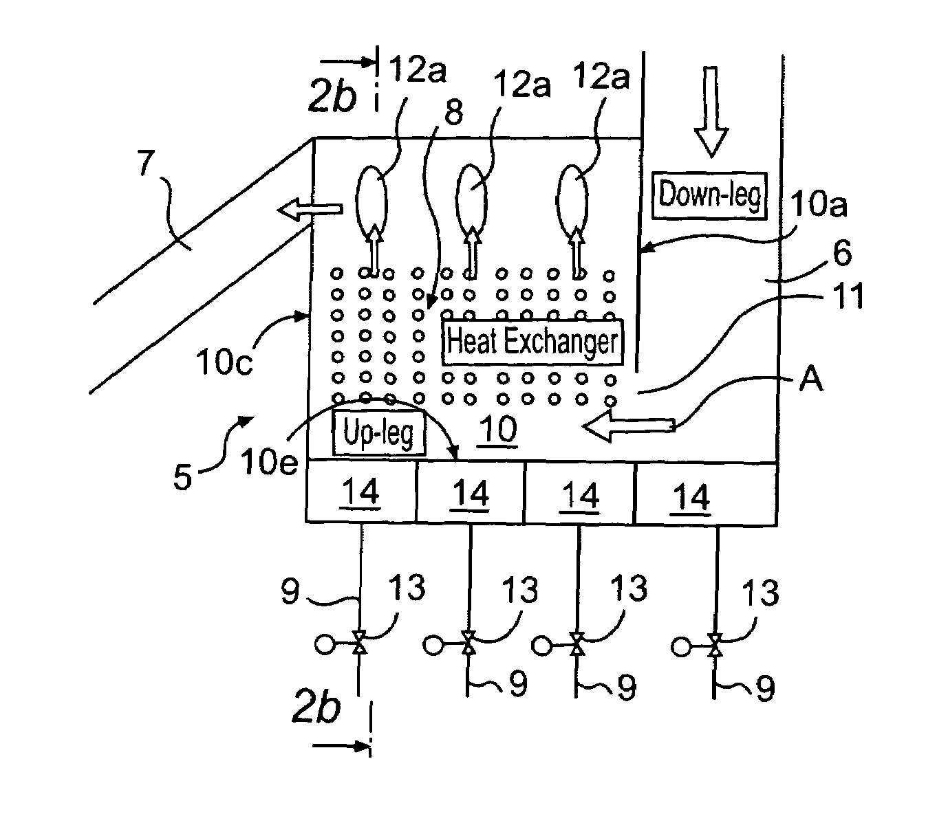
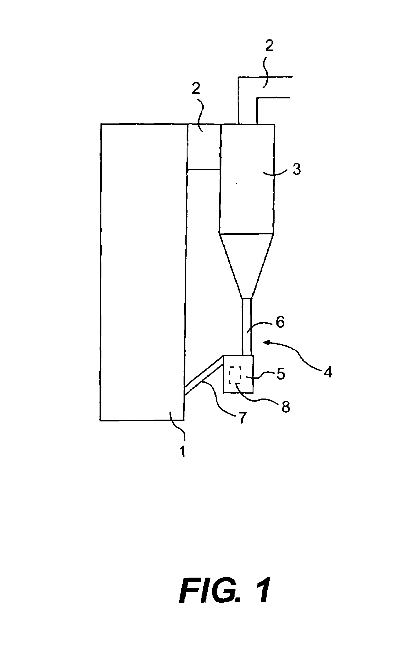
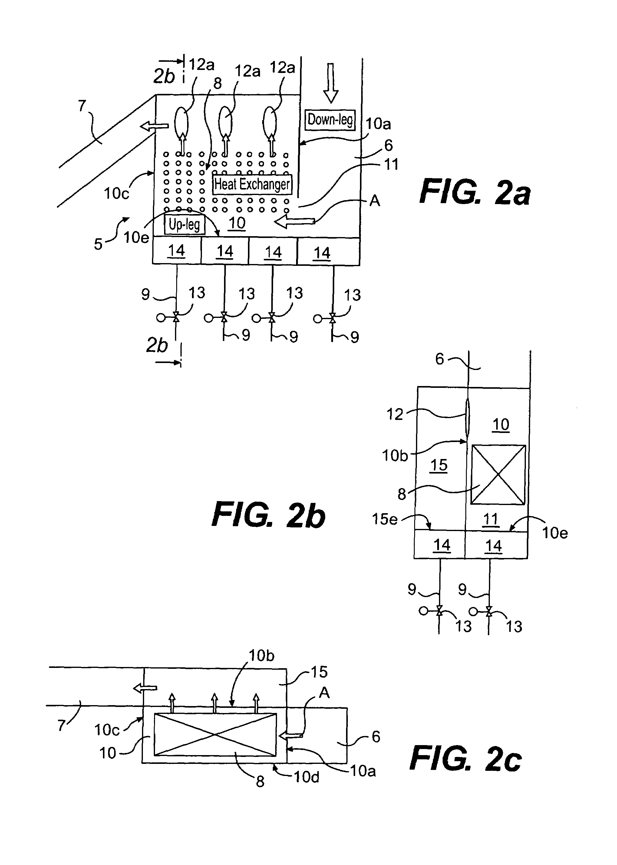
[0019]FIG. 1 shows a typical circulating fluidized bed boiler in which the material forms a so-called circulating fluidized bed (CFB). The boiler comprises a furnace 1, a flue 2 exiting the furnace, and a cyclone placed in the flue and used as a separator 3, which separates the fluidized bed material consisting of solid particles and passing in the flue and returns it to the furnace 1 via a return duct 4. The fluidized bed material may be, for example, inert particulate material, such as sand or crushed rock type, for example diabase. The return duct comprises a loop seal 5. The material travels from the separator 3 into the loop seal 5 via a standpipe or dipleg 6, whose lower end constitutes a so-called down-leg for the loop seal, and it returns from the loop seal 5 into the furnace along a downwardly inclined return conduit 7. The return duct 4 thus consists of the dipleg 6, the loop seal 5 and the return conduit 7. The furnace 1 is used for burning a fuel to produce heat, which i...


PUM


Abstract

A circulating fluidized bed boiler including a furnace, a separator which is connected to the furnace to separate fluidized bed material from a flow leaving the furnace, as well as a return duct between the separator and the furnace to return the separated fluidized bed material into the furnace. The return duct includes a loop seal equipped with a heat exchanger and a supply of fluidizing medium and having an inlet and an outlet, which open into a chamber including the heat exchanger, i.e. a heat exchanger chamber, and are situated at different heights, the outlet being connected through a return conduit to the furnace. The flow cross-section area of the outlet is at an angle to the flow cross-section area of the inlet in such a way that the fluidized bed material is transferred in the heat exchanger chamber in lateral direction with respect to the inlet direction of its inlet flow. The heat exchanger chamber includes individually controllable fluidizing means at different locations in the direction of the horizontal dimension of the flow cross-section area of the outlet.

Description

FIELD OF THE INVENTION[0001]The invention relates to a circulating fluidized bed boiler.BACKGROUND OF THE INVENTION[0002]The operating principle of the circulating fluidized bed boiler is to circulate fluidized bed material in such a way that it is separated from flue gases by a cyclone and is returned via a return duct back to the furnace of the boiler. In the return duct, a loop seal is generally used, which can also be called a sand seal. An example of such a boiler is presented in U.S. Pat. No. 6,237,541 to Alliston et al. This boiler also comprises a heat exchanger chamber which is placed in the furnace and through which the hot fluidized bed material from the loop seal passes before it enters the actual fluidized bed inside the furnace. It is also well known to place the heat exchanger chamber in the actual loop seal and to provide the chamber with a fluidizing air supply, as presented in U.S. Pat. No. 4,813,479; EP patent 518 482; U.S. Pat. No. 5,184,671, and U.S. Pat. No. 5,...

Claims


Application Information

Patent Timeline
Patent Type & Authority Patents(United States)
IPC IPC(8): F23C10/01F22B31/00F23CF23C10/10F23C10/18
CPCF23C10/10F23C10/18F23C2206/103
Inventor KOKKO, ARI
Owner KVAERNER POWER OY
Why Eureka
Try Eureka