Inflate and deflate valve

a valve and deflate technology, applied in the field of valves, can solve the problems of insufficient inflate and deflate valves, no or minimal movement, and often dirty cargo containers, and achieve the effect of avoiding damage to valves and dunnage bags, rapid deflate, and avoiding or significantly reducing the amount of inflated

Inactive Publication Date: 2007-03-27
WASS LLOYD G
View PDF14 Cites 20 Cited by
  • Summary
  • Abstract
  • Description
  • Claims
  • Application Information

AI Technical Summary

Benefits of technology

[0010]Objectives of the invention include providing an improved inflate-deflate valve, and particularly a valve capable of rapid deflation, and designed for a rough environment such that damage to the valve and dunnage bag is avoided or significantly reduced.

Problems solved by technology

The result is that substantially all free space in between the cargo is filled as well as space in between the cargo and the cargo container walls such that no or minimal movement is possible.
Typical inflate and deflate valves are insufficient due to the rough environment and the need for rapid deflation.
The cargo containers are often not clean and include abrasive or rigid walls.
The dunnage bags are often stepped on when deflated thereby damaging the valves and / or causing the valve which often has sharp edges to damage the dunnage bag.

Method used


Image

  • Inflate and deflate valve
  • Inflate and deflate valve
  • Inflate and deflate valve

Examples


Embodiment Construction

[0025]The present invention is a valve embodied as shown in the Figures as an inflate / deflate valve 20. The inflate / deflate valve 20 is a heavy duty valve for use with inflatable devices such as dunnage bags. As noted above, such dunnage bags are used in hostile or rough environments where when deflated the dunnage bags are stacked and compressed into storage drums where the inflate / deflate valves may be crushed or forced against the cuttable or ripable dunnage bag material.

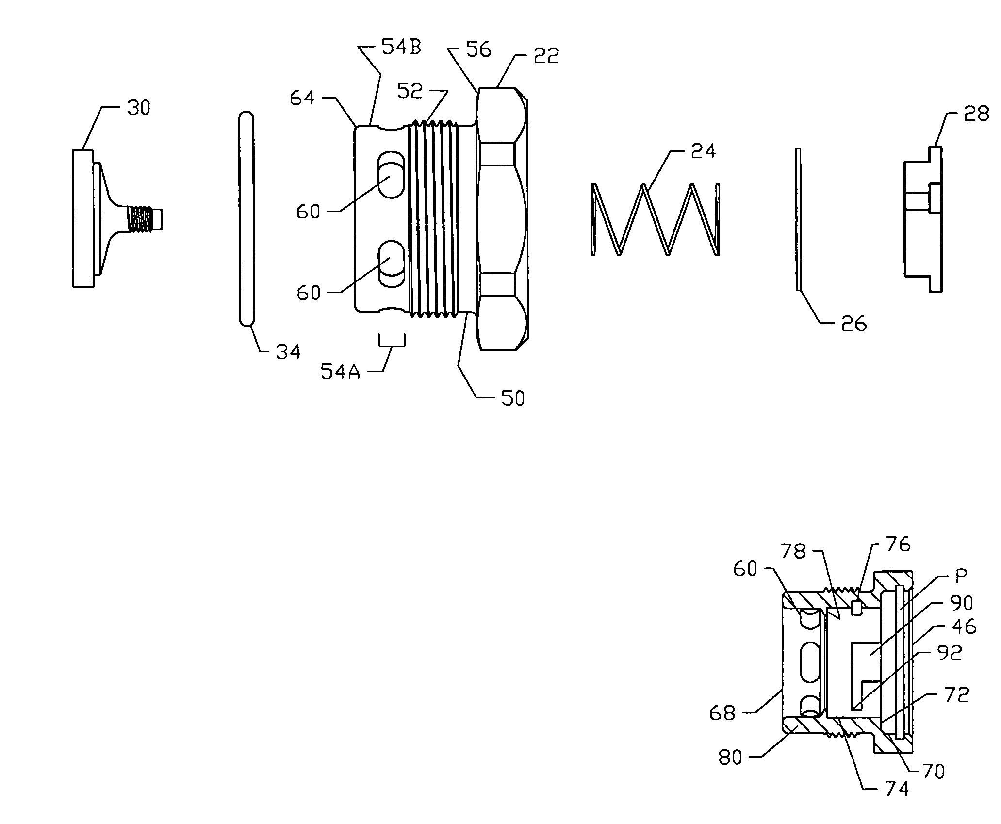
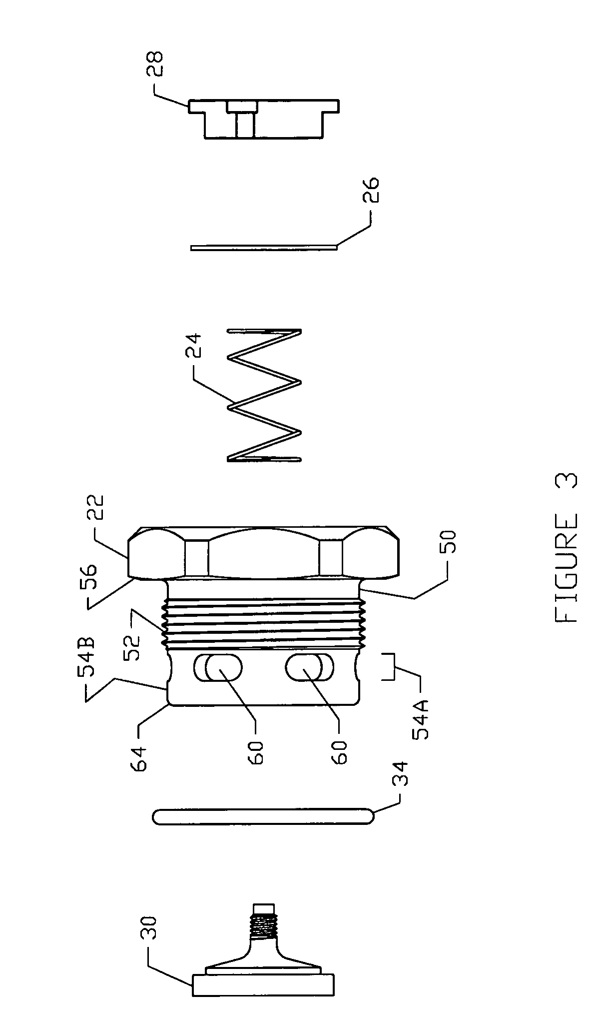
[0026]In the embodiment shown, the inflate / deflate valve 20 is a heavy duty valve having numerous features for overcoming the shortcomings of typical inflate / deflate valves. The inflate / deflate valve 20 includes a valve body 22, a spring 24, an optional washer 26, a spring retainer 28, a poppet 30, poppet seal 32 and an o-ring 34.

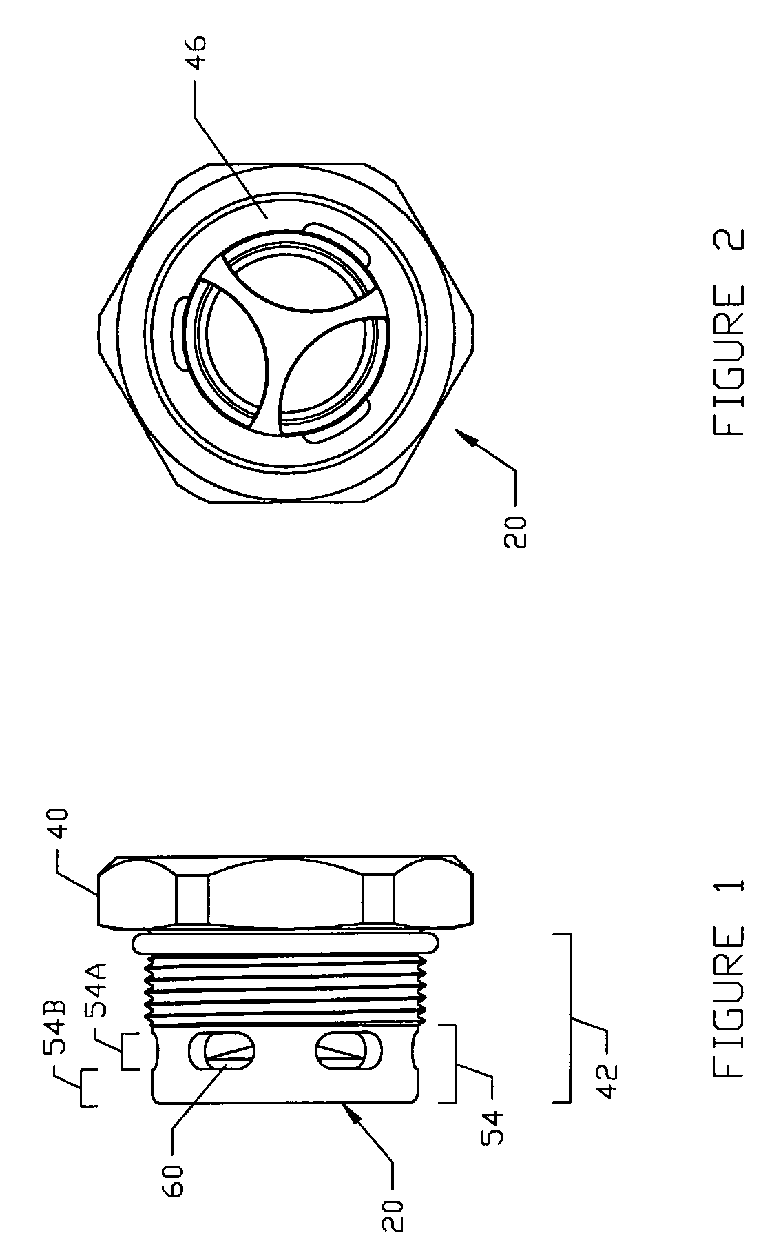
[0027]The valve body 22 as best shown in FIGS. 1–3 includes a head 40 and a neck 42. The head 40 is of a hexagon, octagon or similar design for receiving a standard wrench or other devic...


PUM


Abstract

An inflate/deflate valve of a heavy duty design for use during inflation of inflatable devices such as dunnage bags. Such dunnage bags are used in hostile or rough environments where when deflated the dunnage bags are stacked and compressed into storage drums where the inflate/deflate valves may be crushed or forced against the cuttable or ripable dunnage bag material. As a result, a novel and unique design is provided including a valve body, a spring, an optional washer, a spring retainer, a poppet, poppet seal and an o-ring.

Description

CROSS REFERENCE TO RELATED APPLICATIONS[0001]This application claims priority to U.S. Provisional Patent Application Ser. No. 60 / 310,109 filed on Aug. 6, 2001.BACKGROUND OF THE INVENTION[0002]1. Technical Field[0003]The invention relates to a valve for use during inflation and deflation of inflatable devices. More particularly, the invention is an inflate-deflate valve for use during inflation of inflatable devices such as dunnage bags.[0004]2. Background Information[0005]The ever-growing popularity over the past century of shipping cargo by plane, train, boat, or truck has also led to a growing need to store such cargo in a safe manner to prevent or reduce the chance of breakage, etc. One method of protecting cargo is the dunnage bag which is an inflatable bag used as a spacer in between cargo. In effect, the dunnage bag fills the void in between the cargo thereby giving it nowhere to move or shift to. Dunnage bags are very popular in a number of industries including the paper indu...

Claims


Application Information

Patent Timeline
Patent Type & Authority Patents(United States)
IPC IPC(8): F16K15/20B61D45/00F16K15/02
CPCF16K15/20F16K15/026Y10T137/3584Y10T137/7877Y10T137/7931
Inventor WASS, LLOYD G.
Owner WASS LLOYD G
Why Eureka
Try Eureka