Aircraft high-lift system with overload protection

a technology of overload protection and aircraft, applied in the direction of wing adjustment, aircraft transmission means, couplings, etc., can solve the problems of large and heavy weight, and achieve the effect of improving the protection of aircraft structural elements

Active Publication Date: 2007-03-27
LIEBHERR AEROSPACE LINDENBERG
View PDF9 Cites 23 Cited by
  • Summary
  • Abstract
  • Description
  • Claims
  • Application Information

AI Technical Summary

Benefits of technology

[0004]The task of the within invention is to achieve improved protection of the aircraft structural elements against unacceptable overload in case of locking, with less overall load on the individual components of the drive train in the event of locking.
[0007]Complicated mechanical torque limiters can thereby be eliminated, which represents weight and cost savings compared to the previously existing systems. Additionally, the electrical signal facilitates immediate location of problems. Because the sensor is behind the individual drive station train, fluctuations in the degree of gear efficiency in the measuring chain are eliminated. This improves measurement accuracy considerably. The electronic monitoring of the sensors allows system readiness to be verified at any time and without complicated maintenance work or dismantling of the system. Lastly, the principle of compensation facilitates the gear ratio changes determined by the kinematics of the flap track.
[0009]Accordingly, the drive unit can have an electronic control that is connected with the load sensors, and by means of which an electrical load signal can be fed to the drive system when a load in excess of a tolerance limit is absorbed, so that the drive energy is reduced and the system is in torque equilibrium. In this way there is considerably less load on the drive train components when the system locks, and the components can be lighter compared to existing aircraft high-lift systems.
[0011]The individual load sensors can consist of at least one extension measuring tape positioned inside a hollow pin, which said sensors are designed in standard bridge arrangement. The pin thrust expansion caused by shear load is thus measurable as a change in the bridge resistance. This type of sensor construction can advantageously be designed as hermetically sealed bodies, so that increased resistance to environmental influences can be achieved.
[0014]As a general rule, each segment of the aircraft high-lift flap system is operated by two drive stations. Each drive station bears a portion of the flap loads that is determined by the geometry of the power contacts of air load and driving forces defined. If the flow of energy is interrupted in one of the drive stations, for example by breakage of a component or loss of connection components (a “disconnect”), no more power is sent through the load-sensor-equipped pin. According to one preferred embodiment of the invention, the monitor can thereby recognize an unacceptable change in power ratios and can send the necessary information to the crew, or can trigger the programmed emergency reactions of the drive system.

Problems solved by technology

If an individual segment is blocked, this segment has to take up the full drive energy of the central drive as reaction energy, and accordingly it has to be large and heavy.

Method used


Image

  • Aircraft high-lift system with overload protection
  • Aircraft high-lift system with overload protection

Examples


Embodiment Construction

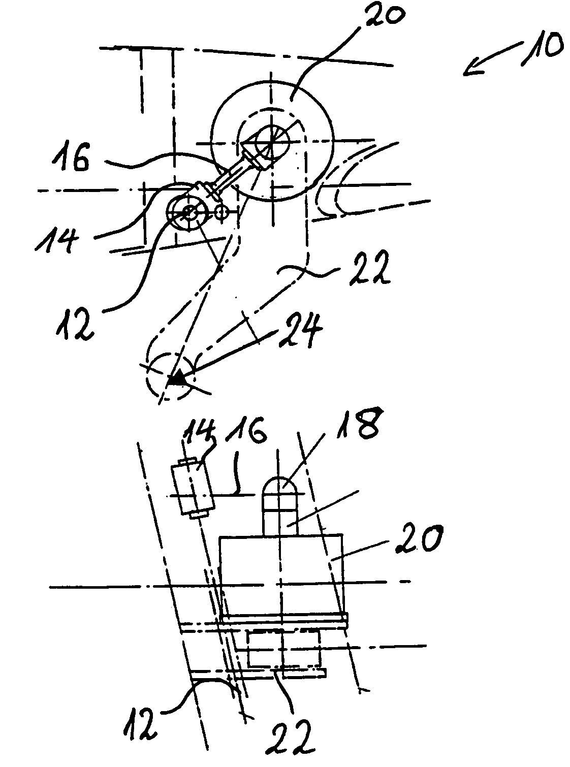
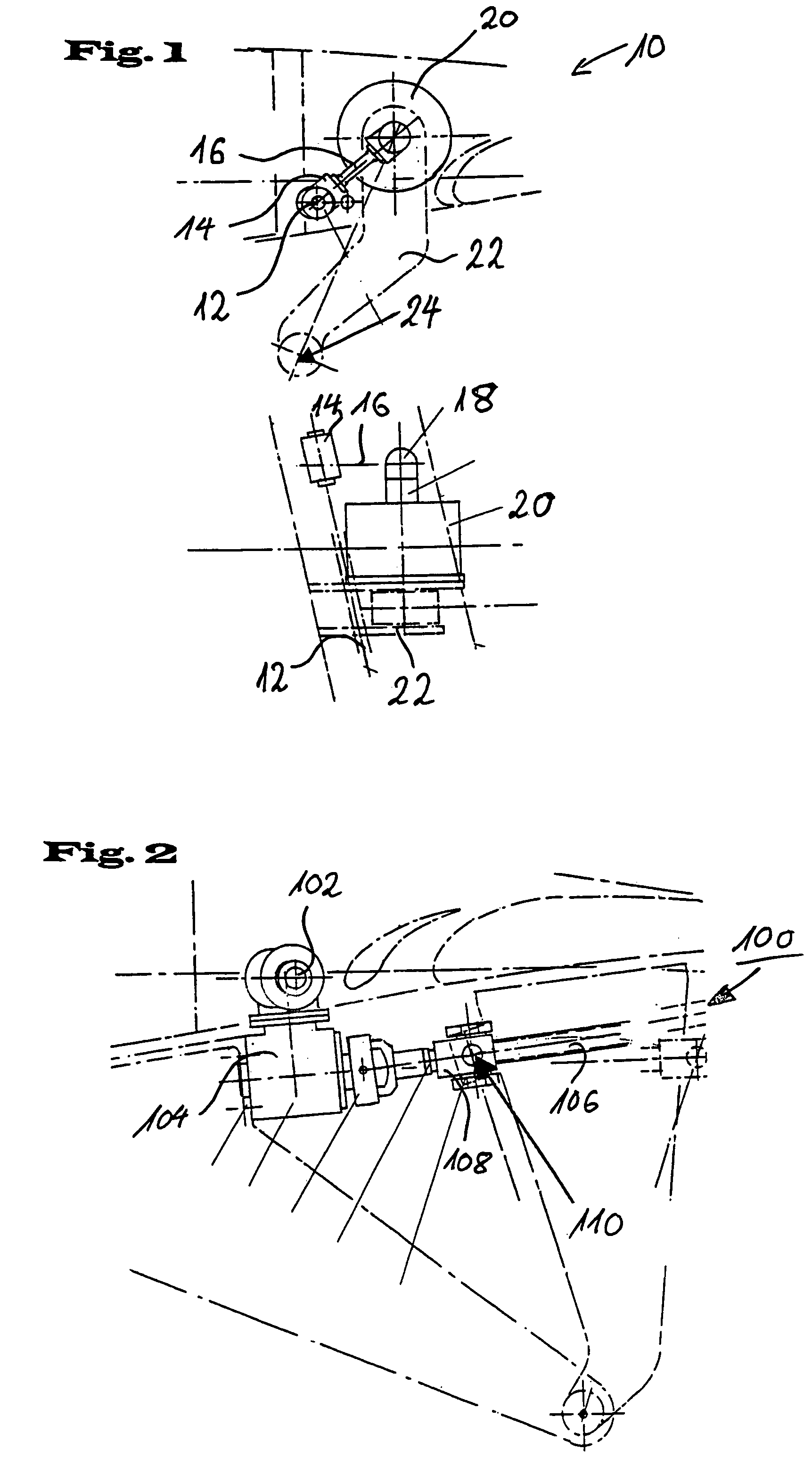
[0019]The embodiment illustrated in FIG. 1 is a typical flap drive station 10 with rotary drive.

[0020]The drive energy is conducted from a central drive shaft 12 via a branch drive 14 to a branch propeller shaft 16. An angular gear 18 forces the drive energy into a step-down gear 20 that operates a lever 22 on the power take-off side. A pin 24 with an integrated load sensor, not illustrated here in greater detail, connects lever 22, in a manner not illustrated here in greater detail, with the drive kinematics of the flap to be operated.

[0021]FIG. 2 shows a second variant embodiment for a typical flap drive station with linear train 100. A ball castor shaft for example can be used as a linear drive. Here the drive energy is derived from a central drive-shaft 102 to a step-down gear 104. On the out-put side the step-down gear 104 drives a stem 106. By means of stem nut 108 the rotary movement is transformed into a linear movement. A pin 110 with an integrated load sensor according to ...


PUM


Abstract

The invention concerns an aircraft high-lift system with a drive system, components for transmitting the drive energy over the entire wing span to drive stations of individual segments of landing flap / slat flap systems, and with overload protection. According to the invention, the overload protection consists of electrical load sensors positioned at the drive-energy in-take points of the individual power trains on the flaps.

Description

BACKGROUND OF THE INVENTION[0001]The invention concerns an aircraft high-lift system with overload protection and having a drive system, and components for transmitting the drive energy over the entire wing span to drive stations of individual segments of landing flap / slat flap systems.[0002]Aircraft high-lift systems with central drive systems for aircraft landing flaps already exist. In these systems the drive energy is distributed by means of rotary shaft systems over the full wing span to corresponding drive stations of the individual segments of the landing flap system or the slat flap system. If an individual segment is blocked, this segment has to take up the full drive energy of the central drive as reaction energy, and accordingly it has to be large and heavy.[0003]Mechanical torque limiters are therefore installed as protective devices on each drive station. These mechanical torque limiters divert the drive energy to the wing structure whenever a specified overload occurs,...

Claims


Application Information

Patent Timeline
Patent Type & Authority Patents(United States)
IPC IPC(8): B64C3/50B64C9/16B64C13/24
CPCB64C9/16B64C13/24Y02T50/44Y02T50/40
Inventor SCHIEVELBUSCH, BERND
Owner LIEBHERR AEROSPACE LINDENBERG
Why Eureka
Try Eureka