Cutting insert with an array of surfaces receiving clamping forces

a technology of clamping force and cutting insert, which is applied in the direction of cutting inserts, shaping cutters, manufacturing tools, etc., can solve the problem of in itself a certain limitation in the choice of geometries, and achieve the effect of efficient locking

Inactive Publication Date: 2007-03-27
SANDVIK INTELLECTUAL PROPERTY AB
View PDF24 Cites 18 Cited by
  • Summary
  • Abstract
  • Description
  • Claims
  • Application Information

AI Technical Summary

Benefits of technology

[0004]Against this background, it is an object of the present invention to provide a new insert design, which on the one hand, is adapted for an efficient locking by means of the above-mentioned type of insert holder having inward-directed as well as downward-directed tensile forces, and which on the other hand leaves a sufficiently large margin on the top side of the cutting insert in order to, e.g., enable desired corner marking or other geometric marking or which enables insertion of more advanced chip breaker geometries directly pressed into the upper chip surface.

Problems solved by technology

This represents in itself a certain limitation as for the choice of geometries for the upper chip side of the cutting insert.

Method used


Image

  • Cutting insert with an array of surfaces receiving clamping forces
  • Cutting insert with an array of surfaces receiving clamping forces
  • Cutting insert with an array of surfaces receiving clamping forces

Examples


Embodiment Construction

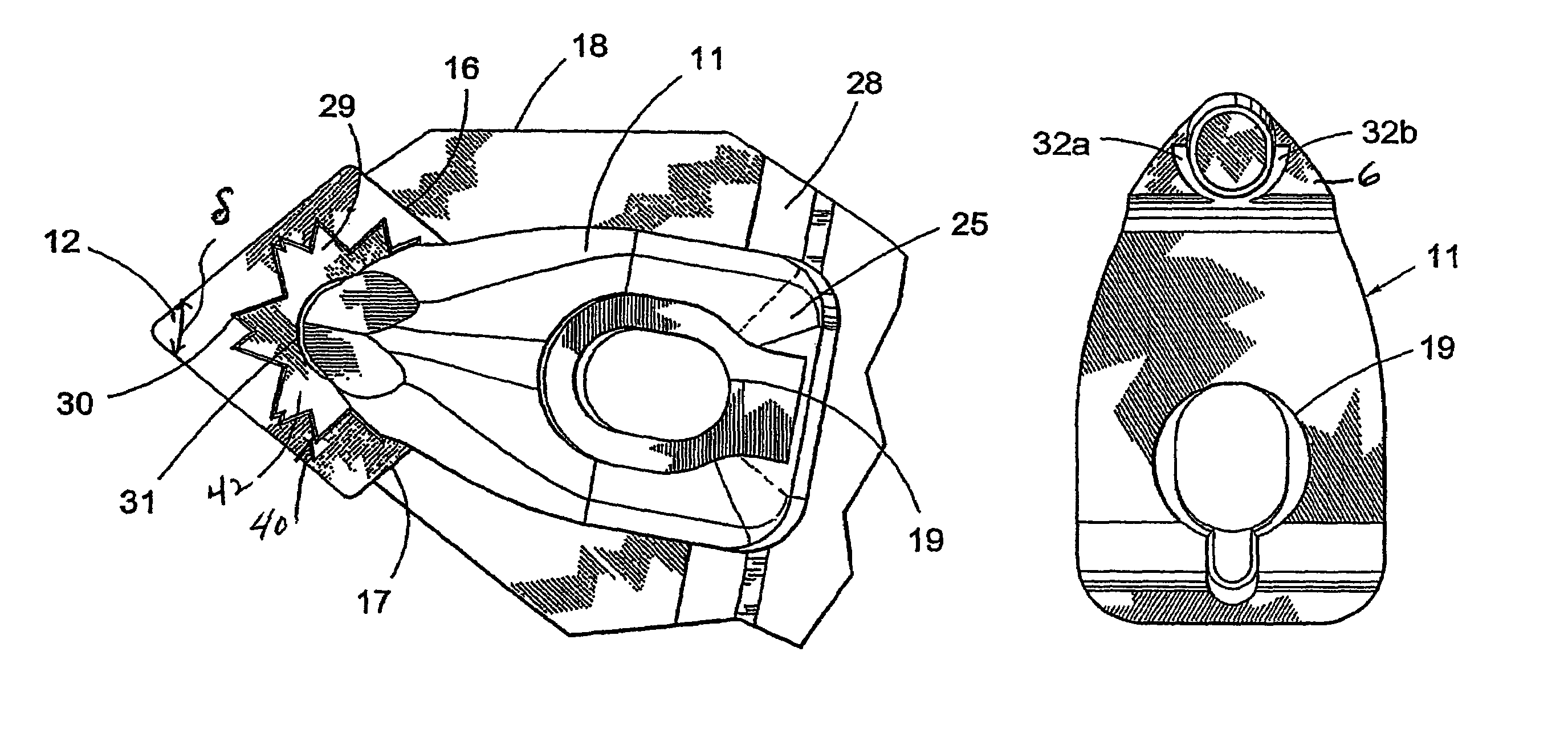
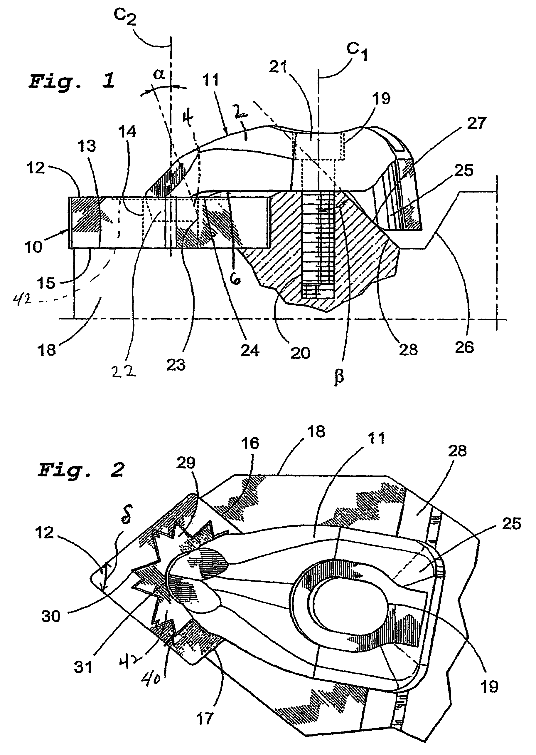
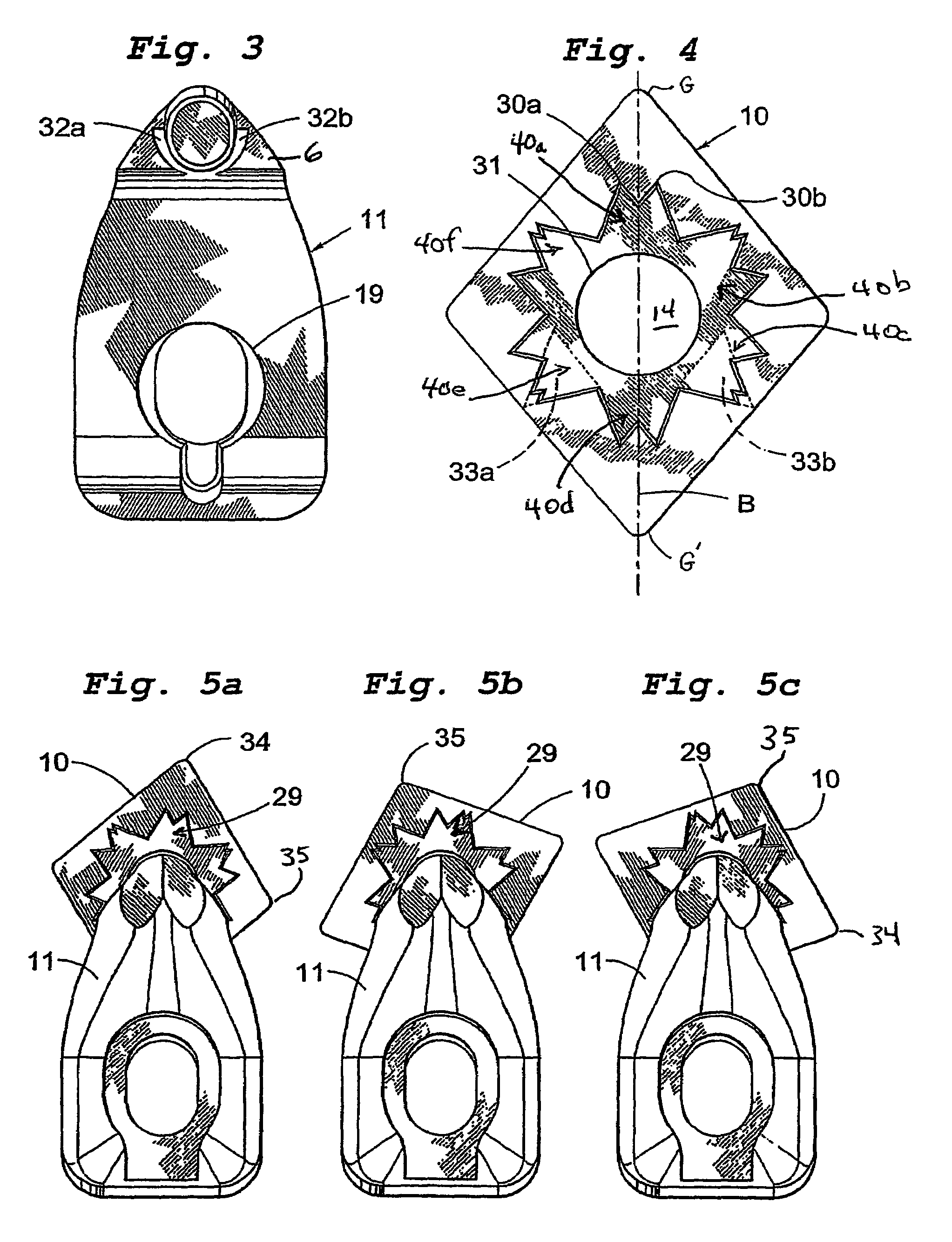
[0017]The indexable insert 10 shown in FIGS. 1–2 is shown in cooperation with a holder clamp 11. The indexable insert has, in this shown embodiment, a rhombic base shape and cutting tip angles δ below 80°. The planar top and bottom surfaces 12 and 13 of the indexable insert, which are mutually parallel, form a right angle to the edge surfaces uniting them. The indexable insert 11 has a central through hole 14, the center axis of which is oriented perpendicularly to the flat surfaces 12 and 13 of the cutting insert. The seating in which the indexable insert 10 is received comprises a bottom support surface 15 and two side support surfaces 16 and 17 upstanding perpendicularly from the surface 15. The bottom support surface 15 may be formed either by an insert holder 18, as in the shown embodiment, or by a separate conventional shim plate (not shown) mounted by means of a suitable fastening means (not shown).

[0018]So as to enable clamping of the indexable insert 10 in the seat of the i...


PUM

PropertyMeasurementUnit
angleaaaaaaaaaa
cutting tip anglesaaaaaaaaaa
radius of curvatureaaaaaaaaaa

Abstract

A cutting insert includes a body that forms top and bottom surfaces, and a center hole intersecting at least the top surface (e.g., a through-hole). A portion of the top surface which extends around the center hole includes an array of projections radiating laterally outwardly around the center hole. A distal end of each projection disposed farthest from the center hole defines a tip of the projection. The projections form at least six tips spaced circumferentially apart. Each tip has a planar top face. A clamp has flat contact surfaces which press downwardly against the planar top faces of respective projections simultaneously as the clamp pulls the insert against an upstanding support surface.

Description

[0001]This application is a Continuation of International Application Serial No. PCT / SE03 / 01749 filed on Nov. 12, 2003, and which published as WO 2004 / 058437 on Jul. 15, 2004.BACKGROUND[0002]The present invention relates to plate-like cutting inserts, intended for chip removing machining of metallic materials, the inserts having a central hole for receiving part of a clamp. Such indexable inserts normally have cutting tip angles below 80° and are usually intended for different types of copying. On the market, there is now a plurality of different types of insert holders, which are especially adapted for such indexable inserts, such as rhombic, rhomboid or isosceles triangular indexable inserts. The material used to make such indexable inserts is normally sintered cemented carbide or ceramics.[0003]A frequently used type of indexable insert is provided with a so-called wiper geometry outside in each active cutting corner. The meaning of this is a radius-modified corner geometry, with...

Claims


Application Information

Patent Timeline
Patent Type & Authority Patents(United States)
IPC IPC(8): B23B29/08B23B27/16
CPCB23B27/1651B23B2200/3618B23B2200/3627Y10T407/229Y10T407/23Y10T407/2272Y10T407/2232
Inventor SJOO, STURESJOBERG, TOMAS
Owner SANDVIK INTELLECTUAL PROPERTY AB
Why Eureka
Try Eureka