Phase plane correlation motion vector determination method

a motion vector and phase plane technology, applied in the field of image and video processing, can solve the problems of inability to obtain clear, high resolution images and video from digital data, and inability to achieve linear interpolation techniques in the temporal domain. achieve the effect of eliminating spurious motion vectors

Inactive Publication Date: 2007-03-27
RGT UNIV OF CALIFORNIA
View PDF8 Cites 29 Cited by
  • Summary
  • Abstract
  • Description
  • Claims
  • Application Information

AI Technical Summary

Benefits of technology

[0010]A phase plane correlation motion vector determination method of an embodiment of the invention identifies images areas in which motion took place. A reference image is shifted by the candidate motion vectors obtained from the phase plane correlation. The shifted reference image is correlated to determine similarity with the current image and to eliminate spurious motion vectors. Candidate motion vectors are validated to determine valid motion vectors and identify problem areas. In a preferred embodiment, a correlation resolution is set to a sub-block size. Sub-blocks of the reference image are shifted by candidate motion vectors for corresponding blocks. Shifted sub-blocks are correlated with sub-blocks of a current image using a sub-block neighborhood to determine valid vector assignments. Where an assignment proves invalid, global motion parameters are determined to assign motion vectors to sub-blocks where correlation fails.

Problems solved by technology

Obtaining clear, high resolution images and video from digital data continues to be a difficult problem faced in the image processing field.
Conventional linear interpolation techniques accordingly are not successful in the temporal domain.
Video signals produce highly redundant information from frame to frame, as many image elements of a predetermined frame will be repeated in a subsequent frame.
Hence, high computational speed is necessary.
To reduce the computation load many researchers have proposed smart searching techniques, but they often reduce the accuracy of the vectors.

Method used


Image

  • Phase plane correlation motion vector determination method
  • Phase plane correlation motion vector determination method
  • Phase plane correlation motion vector determination method

Examples


Embodiment Construction

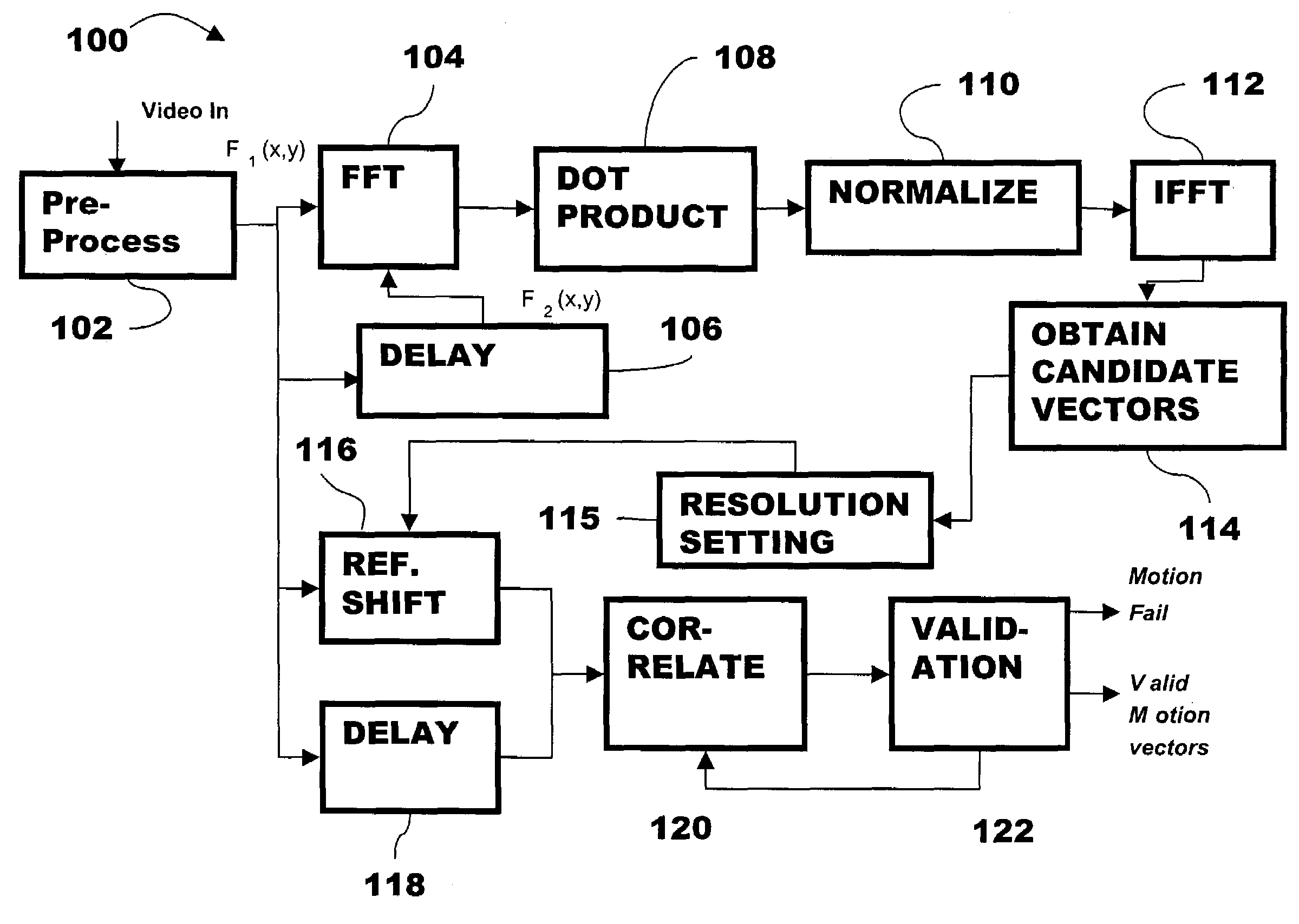
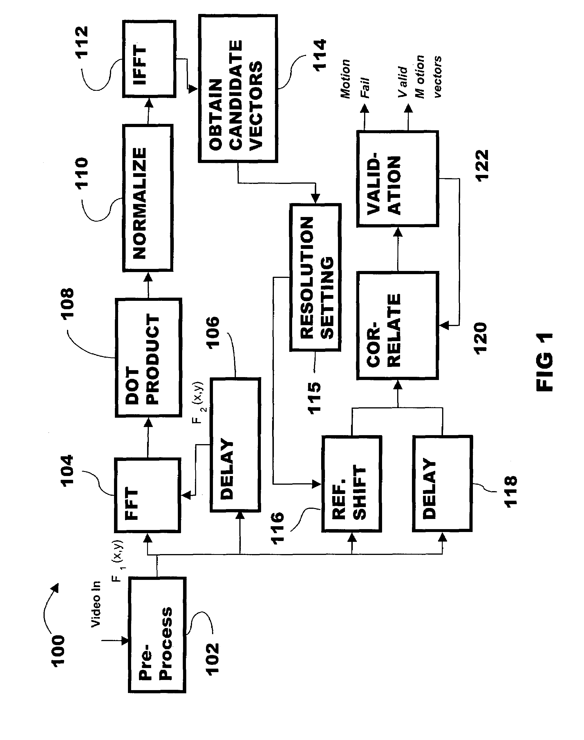
[0017]The invention is directed to phase plane correlation motion vector determination methods and apparatuses. An adaptive validation process obtains, assigns and correlates of motion vectors. In preferred embodiments, vectors obtained by phase plane correlation are considered to be candidate motion vectors. The candidate motion vectors are evaluated to determine whether the candidate motion vectors are valid or spurious in a correlation that uses validated motion vectors and motion vectors from a reference frame. The vectors that do not result in a meaningful correlation with the reference image are identified as spurious motion vectors. Spurious motion vectors may be corrected by reference to global parameters. An image portion including a certain number of spurious motion vectors is identified as problem area requiring further processing. Further processing is conducted on the problem area. Problem areas may be corrected by an interpolation upon recognition of a category of imag...


PUM


Abstract

A phase plane correlation motion vector determination method identifies images areas in which motion took place. A reference image is shifted by the candidate motion vectors obtained from the phase plane correlation. The shifted reference image is correlated to determine similarity with the current image and to eliminate spurious motion vectors. Candidate motion vectors are validated to determine valid motion vectors and identify problem areas. In a preferred embodiment, a correlation resolution is set to a sub-block size. Sub-blocks of the reference image are shifted by candidate motion vectors for corresponding blocks. Shifted sub-blocks are correlated with sub-blocks of a current image using a sub-block neighborhood to determine valid vector assignments. Where an assignment proves invalid, global motion parameters are determined to assign motion vectors to sub-blocks where correlation fails.

Description

FIELD OF THE INVENTION[0001]A field of the invention is image and video processing.BACKGROUND OF THE INVENTION[0002]Obtaining clear, high resolution images and video from digital data continues to be a difficult problem faced in the image processing field. Fundamental data to determine for many applications are motion vector data. Motion vector data provides knowledge of the speed and direction of movements of at least critical parts of the image, e.g., portions of the image determined to be changing over a time period such as from a predetermined image frame to a subsequent image frame. Applications making use of motion vector data include format conversion, de-interlacing, compression, image registration and any others where any sort of temporal interpolation is necessary.[0003]Specific format conversion examples include frame rate conversion, such as the conversion of NTSC video rate to HDTV video rate and the conversion of interlaced video to progressive video. Another format co...

Claims


Application Information

Patent Timeline
Patent Type & Authority Patents(United States)
IPC IPC(8): H04N7/12G06K9/36G06T7/20H04N5/14H04N7/26
CPCG06T7/206H04N19/547H04N5/145G06T7/262
Inventor BISWAS, MAINAKNGUYEN, TRUONG Q.
Owner RGT UNIV OF CALIFORNIA
Why Eureka
Try Eureka