Microwave antenna having a curved configuration

a microwave antenna and configuration technology, applied in the field of microwave antenna probes, can solve the problems of unwanted heating of healthy tissue, uncontrollable non-invasive use of microwave energy, and the inability of antenna probes to provide uniform heating axially and/or radially about the effective length of the probe, so as to prevent tissue from sticking to the antenna

Inactive Publication Date: 2007-03-27
TYCO HEALTHCARE GRP LP
View PDF251 Cites 131 Cited by
  • Summary
  • Abstract
  • Description
  • Claims
  • Application Information

AI Technical Summary

Benefits of technology

[0011]A microwave ablation device is described below which is able to clearly define an ablation region by having the antenna surround at least a majority of the tissue to be ablated without the need to actually penetrate or contact the targeted region of tissue. This is accomplished in part by a microwave antenna probe which has a curved antenna portion ranging in size anywhere from several millimeters to several centimeters depending upon the size of the tissue to be treated. Various conductive materials may be used to fabricate the antenna, such as stainless steel or Nitinol. Moreover, a dielectric coating may be placed over at least a majority of curved antenna to aid with the insertion of the antenna into the tissue as well as to aid in preventing the tissue from sticking to the antenna.
[0012]The curved antenna portion is preferably curved to form a loop or enclosure which is selectively formed large enough for surrounding a region of tissue. When microwave energy is delivered through the feedline, any part of the feedline or antenna that completes the enclosure becomes part of the radiating portion. Rather than radiating directly along the length of the antenna, as one skilled in the art would normally expect, the curved configuration forms an ablation field or region defined by the curved antenna and any tissue enclosed within the ablation region becomes irradiated by the microwave energy. Thus, the curved antenna also serves as a boundary which is able to clearly define what tissue will be irradiated, thereby reducing the amount of undesirable damage to healthy surrounding tissue. Furthermore, the curved antenna also defines a predictable region of tissue outside the irradiated zone which will also be irradiated. This margin of tissue is generally very predictable and serves to treat the tissue a short distance outside the ablation region to ensure complete treatment of the area.
[0018]Additional features may also be employed, e.g., to enhance the safety of the microwave antennas. For instance, a connection mechanism may allow for antenna connection with an outer shell of a conventional or custom connector. Such a feature may be configured to allow an electrical connection upon full deployment of the inner conductor of the curved antenna and no electrical connection during antenna deployment.

Problems solved by technology

However, this non-invasive procedure may result in the unwanted heating of healthy tissue.
Thus, the non-invasive use of microwave energy requires a great deal of control.
However, such typical antenna probes commonly fail to provide uniform heating axially and / or radially about the effective length of the probe.
It is especially difficult to assess the extent to which the microwave energy will radiate into the surrounding tissue, i.e., it is difficult to determine the area or volume of surrounding tissue which will be ablated.
Furthermore, when conventional microwave antennas are inserted directly into the tissue, e.g., cancerous tissue, there is a danger of dragging or pulling cancerous cells along the antenna body into other parts of the body during insertion, placement, or removal of the antenna probe.
However, Miller does not teach any structures for curved microwave antennas or their methods of use for surrounding predetermined regions of tissue for treatment.

Method used


Image

  • Microwave antenna having a curved configuration
  • Microwave antenna having a curved configuration
  • Microwave antenna having a curved configuration

Examples


Embodiment Construction

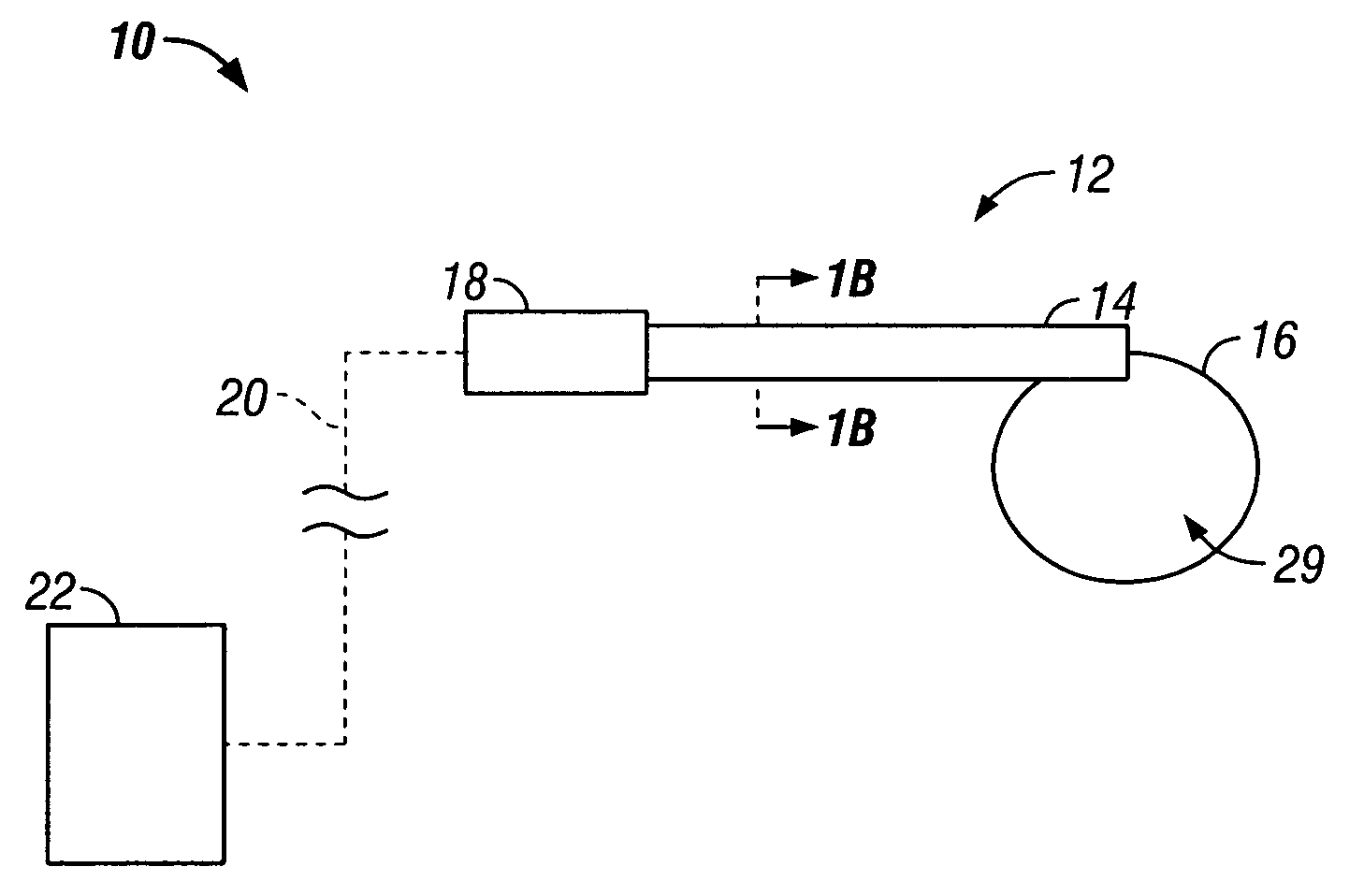
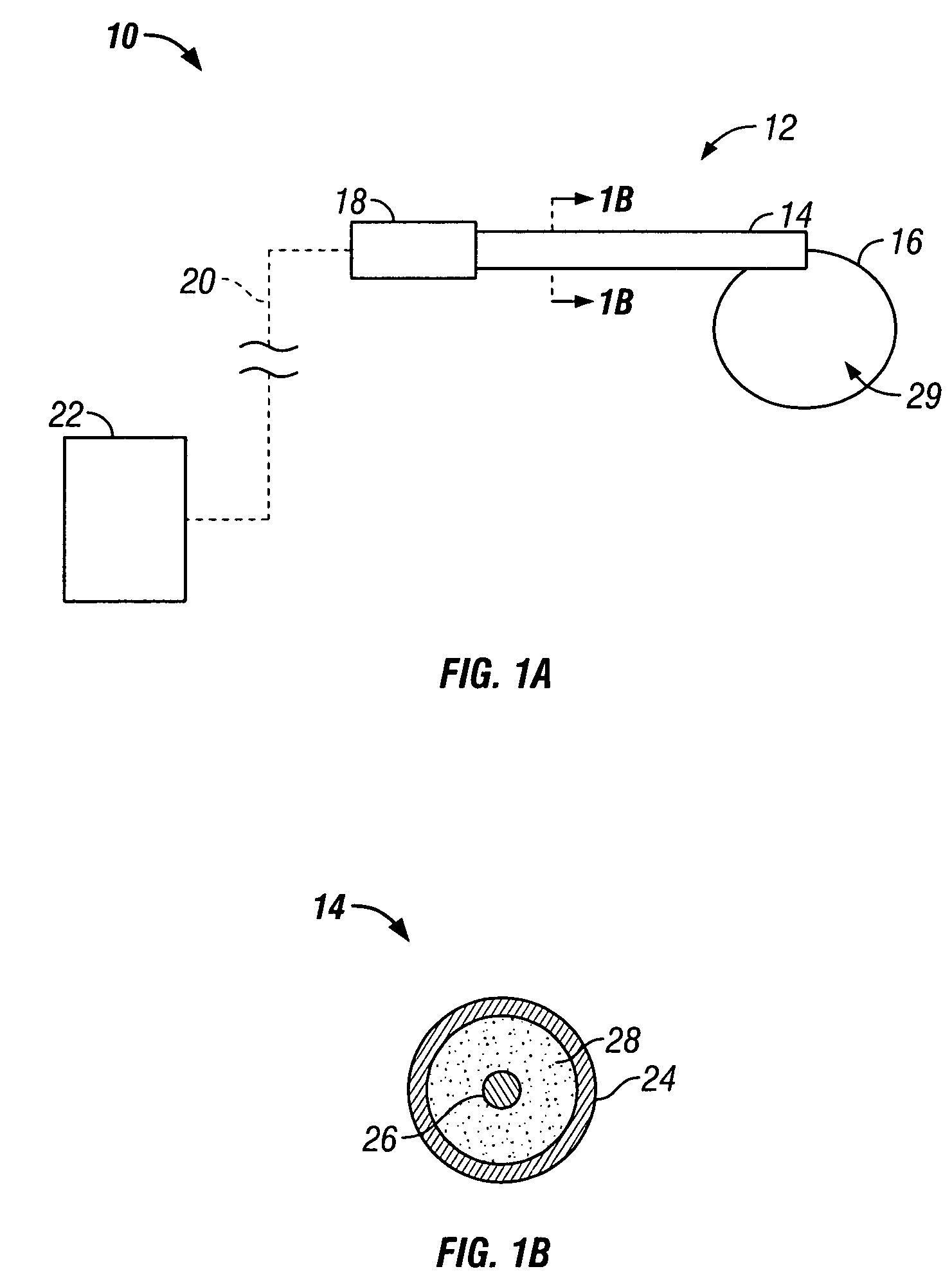
[0060]Microwave ablation devices typically ablate the tissue surrounding the antenna. The present invention clearly defines an ablation region by having the microwave antenna surround at least a majority of the tissue to be ablated without the need to actually penetrate or contact the ablated tissue. Furthermore, the curved microwave antenna allows for the direct control over the outer extent of the thermal lesion created by the device. FIG. 1A shows one variation in microwave antenna assembly 10 which preferably comprises at least microwave antenna 12 electrically connected to generator 22. Microwave antenna 12 preferably comprises shaft or feedline 14 with a distal end from which antenna or inner conductor 16 extends to define the ablation region 29, which is described in detail below. The proximal end of feedline 14 preferably comprises coupler 18 which electrically couples the antenna 12 to generator 22 via power transmission cable 20. The cable 20 is preferably a flexible cable...


PUM


Abstract

A microwave antenna having a curved configuration is described herein. The antenna portion is formed into various shapes whereby the antenna substantially encloses, by a partial or complete loop or enclosure, at least a majority of the tissue to be irradiated. When microwave energy is delivered through the antenna, the curved configuration forms an ablation field or region defined by the curved antenna and any tissue enclosed within the ablation region becomes irradiated by the microwave energy. The microwave antenna is deployed through one of several methods, and multiple curved antennas can be used in conjunction with one another. Moreover, RF energy can also be used at the distal tip of the antenna to provide a cutting tip for the antenna during deployment in tissue.

Description

CROSS-REFERENCE TO RELATED APPLICATIONS[0001]This application claims the benefit of priority of U.S. Provisional Patent Application Ser. No. 60 / 373,190 filed Apr. 16, 2002, which is incorporated herein by reference in its entirety.FIELD OF THE INVENTION[0002]The invention relates generally to microwave antenna probes which may be used in tissue ablation applications. More particularly, the invention relates to microwave antennas which have curved configurations for insertion into tissue.BACKGROUND OF THE INVENTION[0003]In the treatment of diseases such as cancer, certain types of cancer cells have been found to denature at elevated temperatures which are slightly lower than temperatures normally injurious to healthy cells. These types of treatments, known generally as hyperthermia therapy, typically utilize electromagnetic radiation to heat diseased cells to temperatures above 41° C. while maintaining adjacent healthy cells at lower temperatures where irreversible cell destruction w...

Claims


Application Information

Patent Timeline
Patent Type & Authority Patents(United States)
IPC IPC(8): A61N1/00A61B18/18A61B18/14A61B19/00
CPCA61B18/18A61B18/1815A61B19/54A61B18/14A61B18/1477A61B2018/1425A61B2018/1823A61B2018/183A61B2018/1861A61B2019/5408A61B2018/1435A61B90/39A61B2090/3908H01Q11/08A61B2018/00577A61B2018/00601A61B2018/144A61B2018/1846A61B17/29A61B18/1206A61B2018/00589A61B2018/1838A61B2018/1853
Inventor PRAKASH, MANIROSSETTO, FRANCESCAKIM, STEVENSHIU, BRIANFOGARTY, THOMAS J.ZARINS, SASCHA
Owner TYCO HEALTHCARE GRP LP
Why Eureka
Try Eureka