
System and method for identifying a manufacturing tool causing a fault

a technology of manufacturing tools and faults, applied in the field of system and method for identifying the faults of manufacturing tools, can solve the problems of difficult to distinguish the tools causing the fault from one another

Inactive Publication Date: 2007-03-27
KK TOSHIBA
View PDF7 Cites 13 Cited by
  • Summary
  • Abstract
  • Description
  • Claims
  • Application Information

AI Technical Summary

Problems solved by technology

Therefore, when distributions within the surfaces of clustering faults, which may be caused by a plurality of tools, have patterns similar to one another, it is difficult to distinguish the tools causing the fault from one another using only fault unit region patterns indicating the distribution of failure locations on substrates.

Method used


Image

  • System and method for identifying a manufacturing tool causing a fault
  • System and method for identifying a manufacturing tool causing a fault
  • System and method for identifying a manufacturing tool causing a fault

Examples


first embodiment

(First Embodiment)

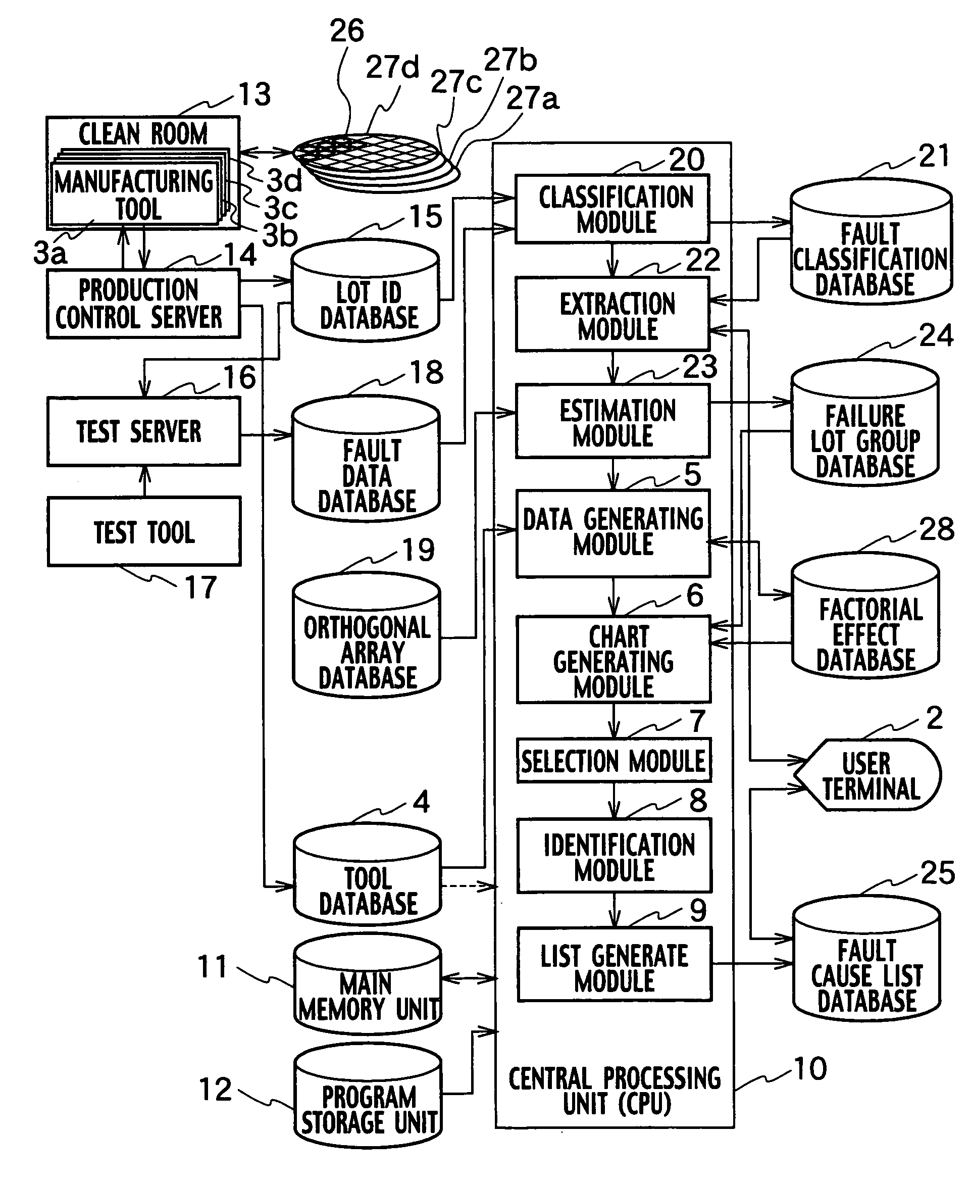
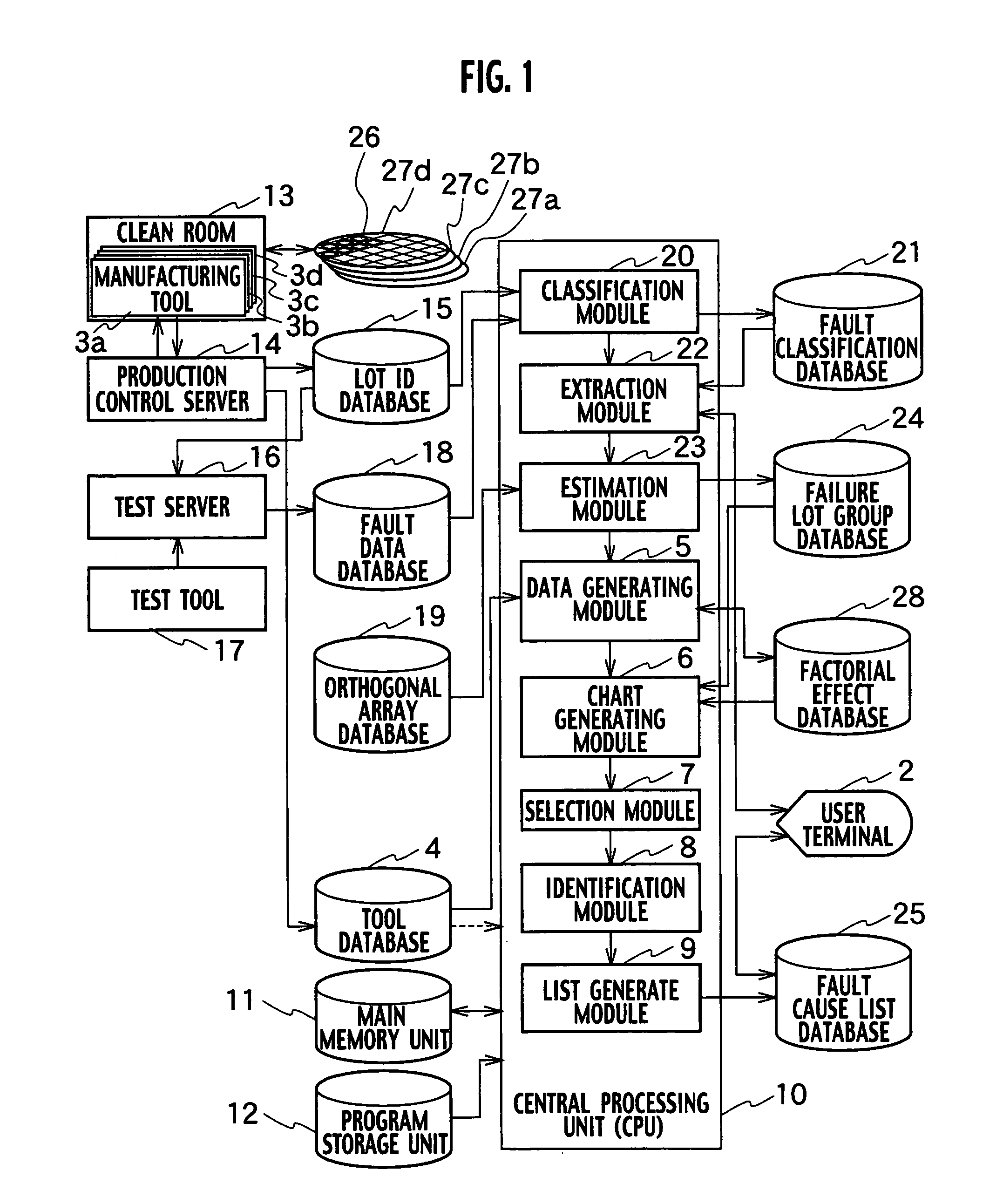
[0030]A system for identifying a manufacturing tool causing a fault according to a first embodiment of the present invention is provided, as shown in FIG. 1, with a central processing unit (CPU) 10 which includes a data generating module 5, a chart generating module 6, a selection module 7, and an identification module 8. The data generating module 5 generates factorial effect data on the basis of information, as to a group of failure lots, by making use of an orthogonal array in which a factor column contains maintenance information and operation information as to a plurality of manufacturing tool groups 3a, 3b, 3c . . . 3q . . . ; and a trial row specifies main effect information by every combinations of levels in the factor column. The chart generating module 6 generates a factorial effect chart on the basis of the factorial effect data. The selection module 7 selects a plurality of failure lots from among the group of failure lots, each resulting from the same ...

second embodiment

(Second Embodiment)

[0105]A system for identifying a tool causing a failure according to a second embodiment of the present invention includes, as shown in FIG. 11, a tool database 4, a yield database 60, a failure lot group database 24, a chart generating module 6, a selection module 7, and an identification module 8. The system for identifying a tool causing a failure shown in FIG. 11 is different from the system shown in FIG. 1 in that the former, i.e. the system in FIG. 11, includes the yield database 60 where the yield information on industrial products is stored, and a CPU 10 includes a lot selection module 59. The tool database 4 stores the maintenance information and the operation information of a plurality of manufacturing tool groups.

[0106]The yield database 60 stores the yield information on industrial products. The failure lot group database 24 stores information on the failure lot group which is estimated based on the test values of a tool-difference analysis calculated ...


PUM


Abstract

A system for identifying a manufacturing tool causing a failure, includes a data generating module generating factorial effect data, based on information on a failure lot group by using an orthogonal array, a chart generating module generating a factorial effect chart based on the factorial effect data, a selection module selecting failure lots caused by the same reason for a failure from among the failure lot group, based on the factorial effect chart, and an identification module identifying a manufacturing tool used as a common tool for the selected plurality of failure lots, based on history information of the manufacturing tool group.

Description

CROSS REFERENCE TO RELATED APPLICATIONS AND INCORPORATION BY REFERENCE[0001]This application is based upon and claims the benefit of priority from prior Japanese Patent Application P2004-096677 filed on Mar. 29, 2004; the entire contents of which are incorporated by reference herein.BACKGROUND OF THE INVENTION[0002]1. Field of the Invention[0003]The present invention relates to a system and a method for identifying a manufacturing tool causing a fault, which analyzes the causes of the reason for a decreased product yield in a manufacturing method and manufacturing of industrial products.[0004]2. Description of the Related Art[0005]A method for analyzing a location of an occurrence of a fault within a surface of a wafer will be described, using an example of a manufacturing process of semiconductor integrated circuits. In the method, the location of an occurrence of a fault within a surface of a wafer is identified, based on data in a storage tool for test results and a storage devic...

Claims


Application Information

Patent Timeline
Patent Type & Authority Patents(United States)
IPC IPC(8): G06F19/00G05B19/418G06F11/30G06Q50/00G06Q50/04H01L21/66
CPCG05B19/4184G05B2219/32222G05B2219/31356Y02P90/02
Inventor MATSUSHITA, HIROSHIKADOTA, KENICHI
Owner KK TOSHIBA
Learn More