Hand-held apparatus for installing flashover protection covers on energized electrical conductors

a technology for protecting covers and electrical conductors, which is applied in the direction of cables, special-purpose vessels, manufacturing tools, etc., can solve the problems of increasing the potential for flashover caused by uninsulated conductors contacting each other or other objects, and the clearance between conductors and/or other grounded objects may not be sustainable, etc., and achieves the effect of convenient us

Inactive Publication Date: 2007-04-03
TE CONNECTIVITY CORP
View PDF22 Cites 11 Cited by
  • Summary
  • Abstract
  • Description
  • Claims
  • Application Information

AI Technical Summary

Benefits of technology

[0019]Hand-held devices according to the present invention are particularly advantageous because they are lightweight and easy to use. With a single arm motion, the edge portions of a cover surrounding an energized conductor or other structure can be joined together. As such, flashover protection covers can be installed on energized conductors and equipment safely and quickly.

Problems solved by technology

Flashover may result if contact is made between two hot conductors or between a hot conductor and ground.
Although uninsulated conductors may be less expensive to install than insulated conductors, potentially costly problems may arise from the use of uninsulated conductors.
Adequate clearances between conductors and / or other grounded objects may not be sustainable during adverse weather conditions (i.e., storms and high winds).
As a result, the potential for flashover caused by uninsulated conductors contacting each other or other objects may be increased.
In addition, falling trees and tree branches may cause contact between hot conductors and ground which may result in flashover.
Flashover may result in power outages which are undesirable to electric power suppliers and to consumers.
Unfortunately, the cost of replacing uninsulated conductors with insulated conductors may be expensive.
Furthermore, an interruption in the delivery of power may be required to replace uninsulated conductors.
This may be economically disadvantageous to an electric power supplier as well as being undesirable to electric power consumers.
Unfortunately, there are drawbacks associated with installation methods for each of these types of covers.
Thick rubber tubing can be somewhat bulky and difficult to install.
Such electrical power service interruptions may be economically disadvantageous to an electric power supplier as well as being undesirable to electric power consumers.
The use of a torch or other heat source, particularly around substation equipment, is generally undesirable and can be labor intensive.
Unfortunately, this method can be a somewhat labor intensive process as well.
Unfortunately, operations for joining the edges together on these types of covers can be labor intensive.

Method used


Image

  • Hand-held apparatus for installing flashover protection covers on energized electrical conductors
  • Hand-held apparatus for installing flashover protection covers on energized electrical conductors
  • Hand-held apparatus for installing flashover protection covers on energized electrical conductors

Examples


Embodiment Construction

[0033]The present invention now will be described more fully hereinafter with reference to the accompanying drawings, in which preferred embodiments of the invention are shown. This invention may, however, be embodied in many different forms and should not be construed as limited to the embodiments set forth herein; rather, these embodiments are provided so that this disclosure will be thorough and complete, and will fully convey the scope of the invention to those skilled in the art. Like numbers refer to like elements throughout the discussion of the drawings.

Flashover Protection Covers

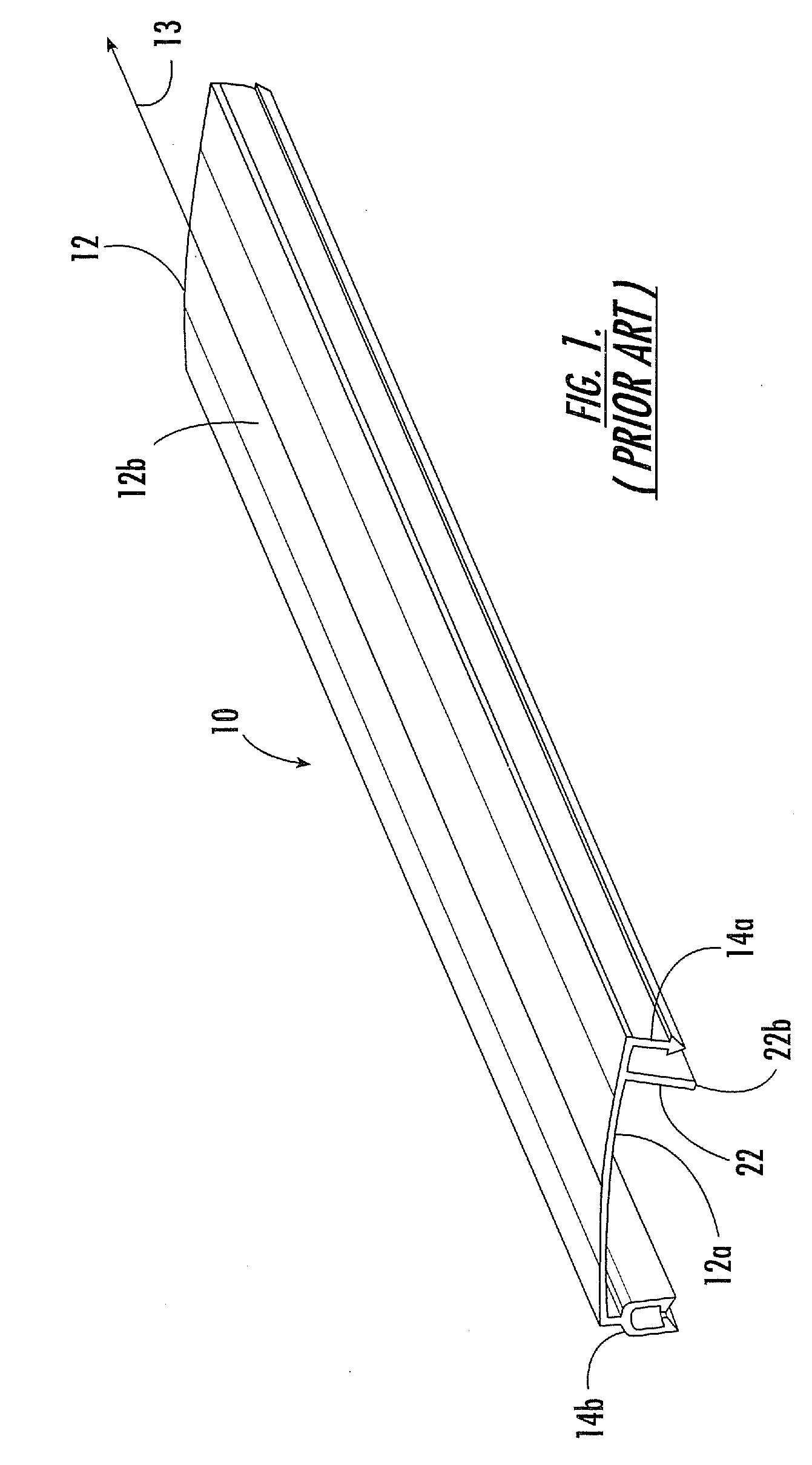
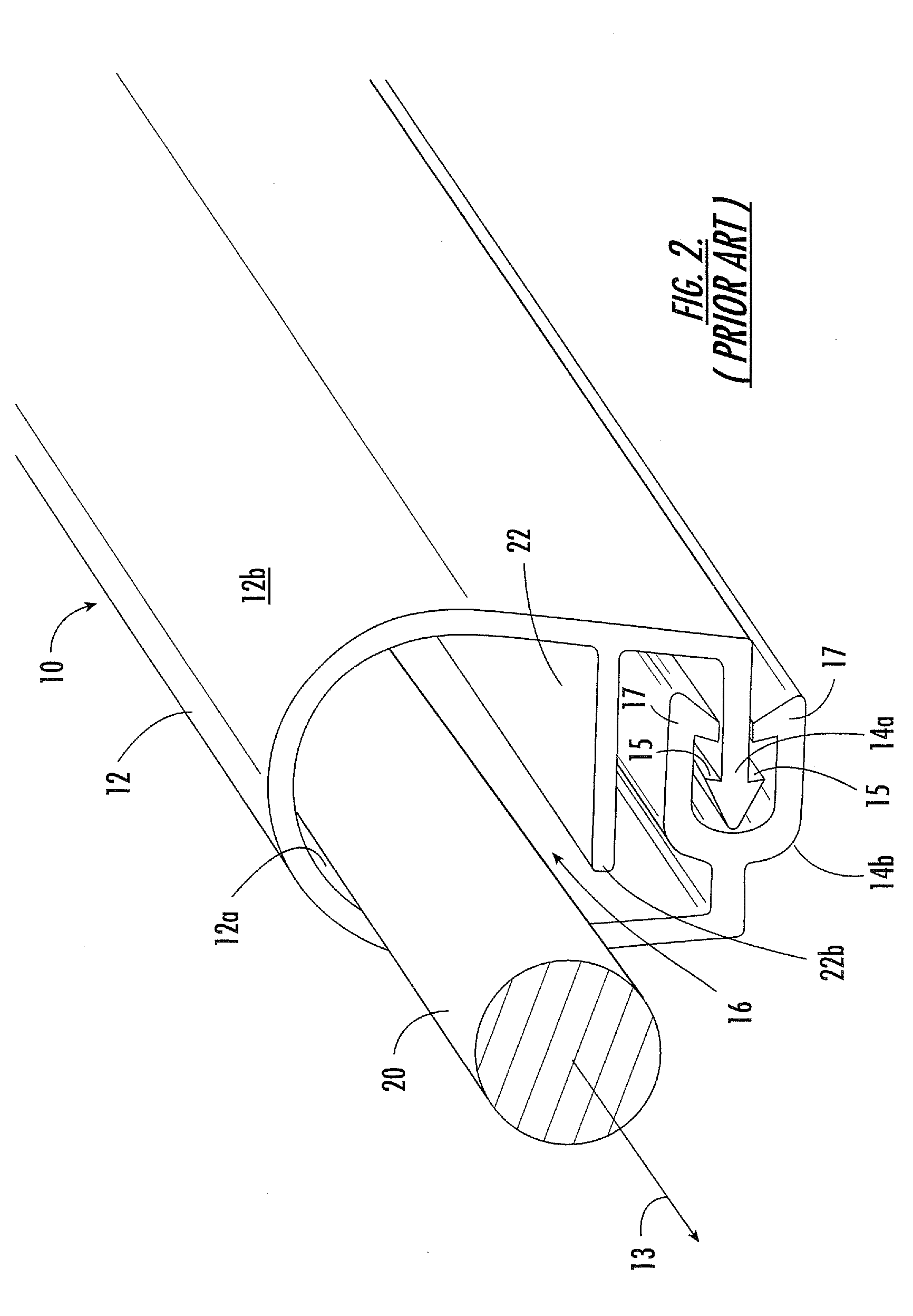
[0034]Referring now to FIGS. 1–2, an exemplary flashover protection cover 10 for covering an energized conductor, or other structure, is illustrated in an uninstalled configuration (FIG. 1) and in an installed configuration (FIG. 2). The flashover protection cover 10 includes an elongated flexible panel 12 that defines a longitudinal direction (indicated by arrow 13). The flashover protection cover ...


PUM

PropertyMeasurementUnit
voltageaaaaaaaaaa
flexibleaaaaaaaaaa
electrical conductoraaaaaaaaaa

Abstract

Hand-held devices that can be used to quickly install flashover protection covers around energized electrical conductors and equipment are provided. Each device includes a guide assembly that defines a pair of spaced-apart, converging passageways that are configured to slidably receive the elongated edge portions of a flexible panel therethrough. The converging passageways force together the opposite edge portions of a flexible panel being advanced through the guide assembly.

Description

RELATED APPLICATION[0001]This application is a continuation-in-part of U.S. patent application Ser. No. 09 / 415,828, filed on Oct. 12, 1999, now U.S. Pat. No. 6,219,907, which is hereby incorporated herein in its entirety by reference.FIELD OF THE INVENTION[0002]The present invention relates generally to insulating covers and, more particularly, to devices for installing insulating covers.BACKGROUND OF THE INVENTION[0003]Electrical power may be transmitted from a generation source to consumers via overhead conductors strung between towers or poles. Electrical power is conventionally transmitted in phases wherein multiple conductors are utilized. One or more of these conductors may be a “hot” conductor that carries a specified amount of alternating current electric power. Flashover may result if contact is made between two hot conductors or between a hot conductor and ground. Non-grounded contact with a hot conductor, such as when a bird sits upon a hot conductor, typically does not r...

Claims


Application Information

Patent Timeline
Patent Type & Authority Patents(United States)
IPC IPC(8): B23P19/00H02G3/04H02G1/02H02G7/00
CPCB25B33/00H02G1/00Y10T29/5327Y10T29/53213Y10T29/53657Y10T29/532Y10T29/5187H02G1/02H02G3/0487H02G7/00Y10T29/5191Y10T29/49117H02G3/04
Inventor FRYE, TERRY EDWARD
Owner TE CONNECTIVITY CORP
Why Eureka
Try Eureka