Multi-resolver rotation angle sensor with integrated housing

a technology of rotation angle sensor and integrated housing, which is applied in the direction of simultaneous indication of multiple variables, instruments, and mechanical means, and can solve problems such as the inability to easily deform printed circuits thereon

Active Publication Date: 2007-04-03
MINEBEAMITSUMI INC
View PDF17 Cites 5 Cited by
  • Summary
  • Abstract
  • Description
  • Claims
  • Application Information

AI Technical Summary

Benefits of technology

[0021]In view of the above-mentioned limitations, the multi-resolver rotation angle sensor of the present invention includes a housing with a high precision structure, a terminal that connects to a resolver stator and that does not cause deformation or loosening of terminal pins from an associated stator insulator, and a connection structure between resolver stators and a signal output line that is not affected by thermal stress.
[0024]Regarding the connection structure, a connection substrate is fastened to the housing for connecting respective lead lines of stator windings to an external signal output line or lines. The lead lines of the stator windings are connected to the connection substrate either directly or via flexible connecting lines such as magnet wires or flexible printed circuit substrates that extend from the relaying substrate to which the lead lines are connected. The lead lines, magnet wires or flexible printed circuit substrates provide absorb distortion and vibration generated by thermal stress to maintain the external electrical connection between the stator windings and the connection substrate.

Problems solved by technology

Because the terminal pins are fastened to the printed circuit substrate, the printed circuits thereon are not easily deformed, and the terminal pins are not loosened, even at high temperatures.

Method used


Image

  • Multi-resolver rotation angle sensor with integrated housing
  • Multi-resolver rotation angle sensor with integrated housing
  • Multi-resolver rotation angle sensor with integrated housing

Examples


Embodiment Construction

[0033]The rotation angle sensor of the present invention will now be described in detail in accordance with the drawings. Illustration and description of components such as resolver rotors are omitted where not necessary for one skilled in the art to understand the present invention. The structure of the housing, the supporting structure of the terminal pins and the overall rotation angle sensor structure will be described in order.

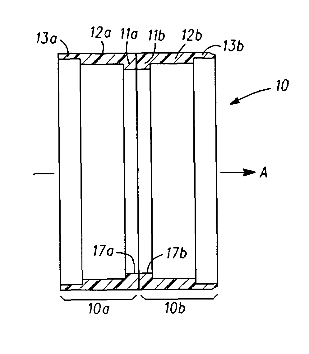
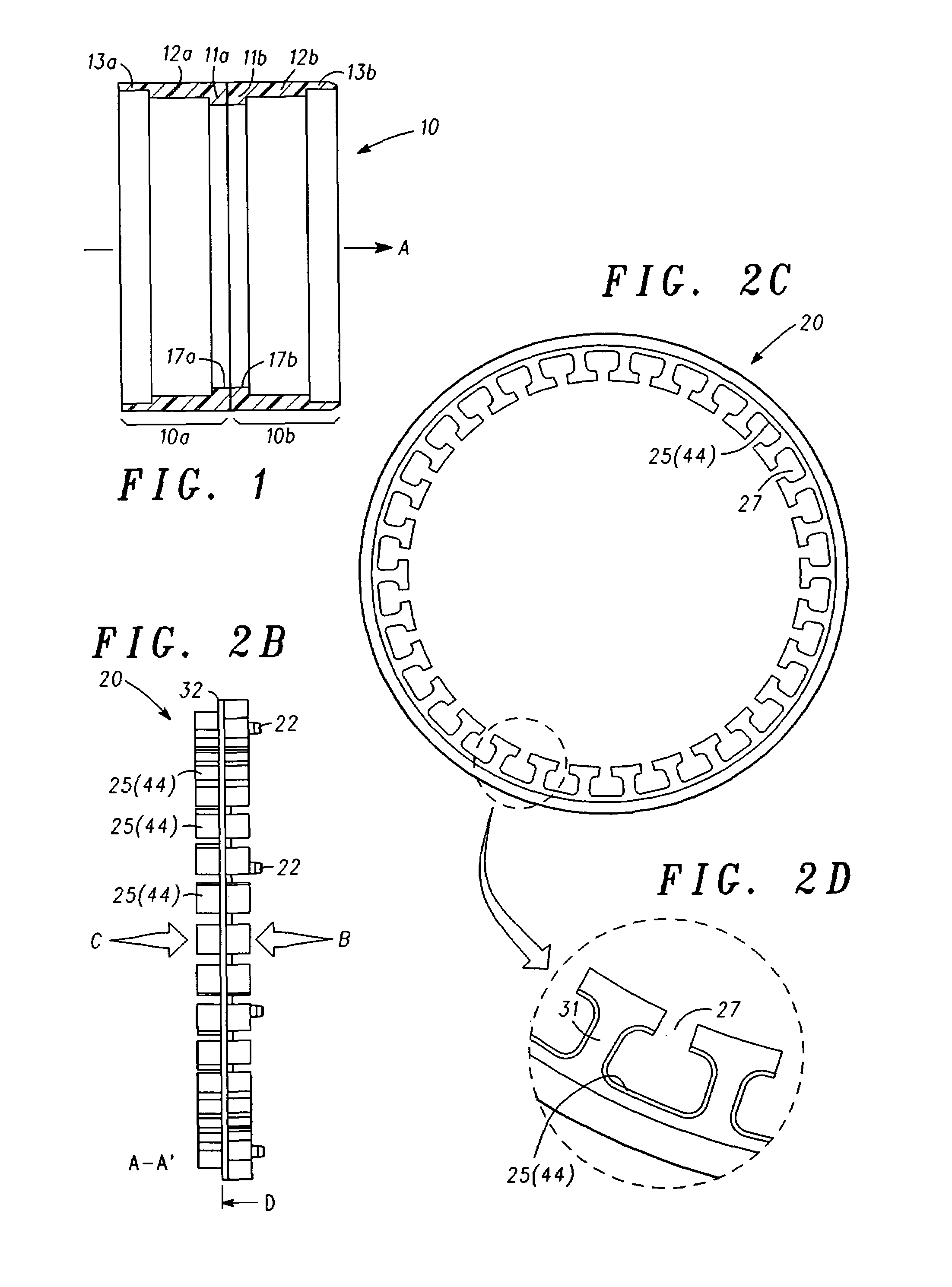
[0034]FIG. 1 is a cross-sectional view of the housing 10 of the multi-resolver rotation angle sensor of the present invention, with the arrow A defining the direction through which a rotating member (not shown; see torsion bar 103 in FIG. 1 for an example of such a rotating member) having a rotation angle to be sensed by the rotation angle sensor of the present invention extends through the housing 10. The housing 10 is formed from a stainless steel or an aluminum alloy and includes divisional housings 10a, 10b that are welded together by aligning and adj...


PUM

PropertyMeasurementUnit
rotation angleaaaaaaaaaa
shapeaaaaaaaaaa
flexibleaaaaaaaaaa

Abstract

A rotation angle sensor includes: (a) a multi-resolver housing with a high precision structure; (b) stator terminals that do not cause deformation or loosening of terminal pins from the substrates to which they are attached; and (3) a signal line connection structure that is not affected by thermal stress. The housing (10) includes divisional housings (10a, 10b), and one resolver is installed in each of the divisional housings (10a, 10b). The divisional housings (10a, 10b) are assembled by aligning respective openings therein in an axial direction. The lead lines of stator windings are connected to printed circuit substrates (51) installed on insulators (20a, 20b), and pins (54) connect the printed circuit substrates (51) to a connecting signal output line via flexible connectors (61, 64).

Description

CROSS REFERENCE TO RELATED APPLICATION[0001]This application is based on and incorporates by reference Japanese Patent Application No. 2003-201485, which was filed on Jul. 25, 2003.BACKGROUND OF THE INVENTION[0002]The present invention relates to a rotation angle sensor incorporating at least two resolvers, and in particular to a rotation angle sensor that detects the amount of relative rotation of an input axle and an output axle of, for example, an automobile power steering device that manipulate a steering device torsion bar as a result of their relative rotation.[0003]A rotation angle sensor may be used in conjunction with a power steering device to detect a relative turning angle of an automobile steering wheel for steering control-related applications. Specifically, the sensor detects the amount of relative rotation of an input axle and an output axle arranged on the steering device torsion bar when resolvers respectively rotate the input axle and the output axle.[0004]As show...

Claims


Application Information

Patent Timeline
Patent Type & Authority Patents(United States)
IPC IPC(8): G01B7/30G01D5/20G01D5/245G01D11/24G01L3/10G01L5/22H02K24/00
CPCG01D5/2013G01D11/245
Inventor KOYAMA, TOSHISADAMATSUURA, MUTSUMISANO, TAKASHIOSANAI, YOSHIHITO
Owner MINEBEAMITSUMI INC
Why Eureka
Try Eureka