Device for inspecting micro structure, method for inspecting micro structure and program for inspecting micro structure

a micro-structure and micro-structure technology, applied in the direction of fluid tightness measurement, vibration measurement in solids, blast furnaces, etc., can solve the problems of high cost, difficult to carry out high-precision inspection, complex, etc., and achieve the effect of simple system and high precision

Inactive Publication Date: 2005-12-22
OCTEC INC +1
View PDF13 Cites 8 Cited by
  • Summary
  • Abstract
  • Description
  • Claims
  • Application Information

AI Technical Summary

Benefits of technology

[0009] The present invention is achieved in order to solve the above-described problem, and an object thereof is to provide a method, a unit and a program for inspecting a structure having a microscopic moveable part with high precision and in a simple system.
[0041] In accordance with a method, a unit and a program for inspecting a micro structure according to the present invention, test sound wave is supplied to a micro structure and the movement of the moveable part of the micro structure is detected, and thereby, the property thereof are evaluated. The moveable part of the micro structure is moved by means of air vibrations using sound wave, which is compression wave, so that the property thereof can be evaluated, and therefore, the micro structure can be inspected with a simple system.

Problems solved by technology

Though the property of an acceleration sensor must be evaluated by carrying out microscopic adjustment, even in the case where a device is changed by blowing air to the device as shown in the above-described gazette, it is extremely difficult to carry out inspection with high precision by controlling the amount of gas flow, and at the same time uniformly blowing a gas against the device, and a complex, expensive tester must be provided, even when such inspection is implemented.

Method used


Image

  • Device for inspecting micro structure, method for inspecting micro structure and program for inspecting micro structure
  • Device for inspecting micro structure, method for inspecting micro structure and program for inspecting micro structure
  • Device for inspecting micro structure, method for inspecting micro structure and program for inspecting micro structure

Examples


first embodiment

Modification of First Embodiment

[0122] According to a modification of the first embodiment of the present invention, a case is described where property of a micro structure are evaluated in a system that is different from the one described in the first embodiment.

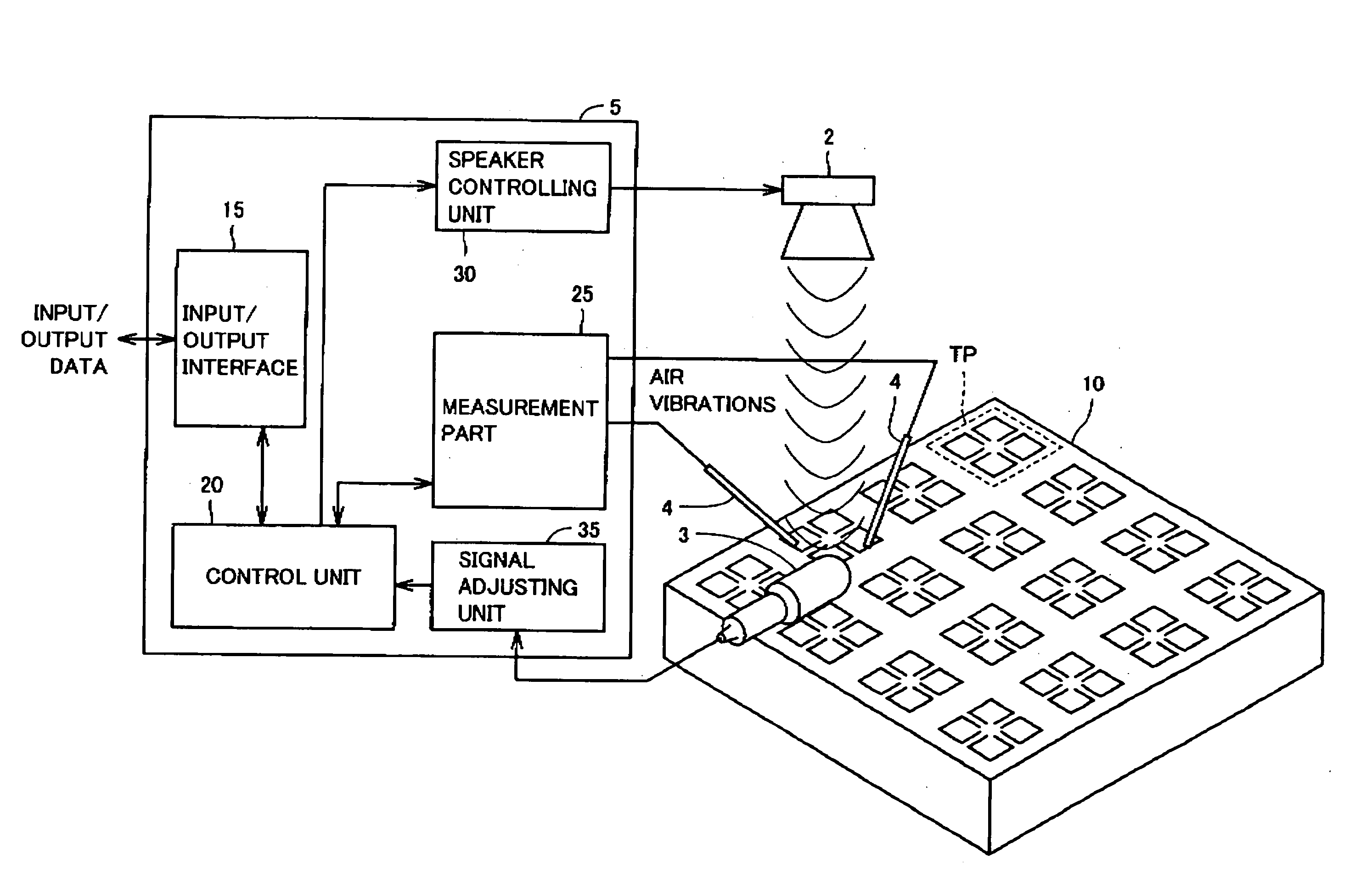
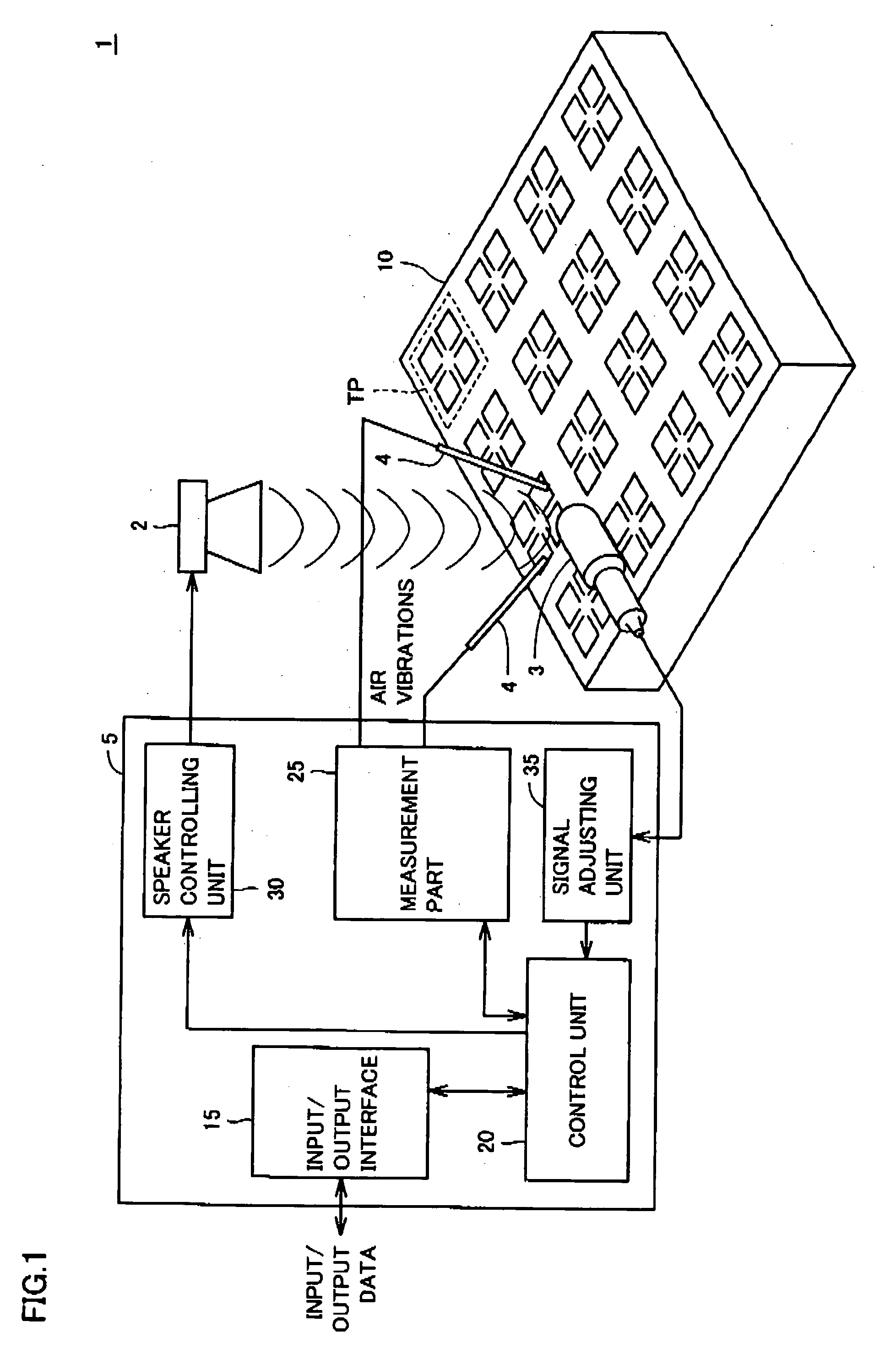
[0123] With reference to FIG. 11, inspection system 11 according to the modification of the first embodiment of the present invention is different from that of the first embodiment in the point where tester 5 is replaced with tester 6. Tester 6 is different from tester 5 in the point where microphone 3 and signal adjusting unit 35 are not present in tester 6. The other parts are the same, and the descriptions thereof are not repeated.

[0124] With reference to the flowchart of FIG. 12, a method for inspecting a micro structure according to the modification of the first embodiment of the present invention is described.

[0125] With reference to FIG. 12, inspection (testing) of a micro structure is started as described above (...

second embodiment

[0133] An inspection method and an inspection device for implementing an inspection with higher precision are described according to a second embodiment of the present invention.

[0134] With reference to FIG. 13, an inspection system 1# according to the second embodiment of the present invention is different from inspection system 1 in the point where tester 5 has been replaced with tester 5#. Other parts are the same as in inspection system 1 that is described in FIG. 1, and therefore, the detailed descriptions thereof are not repeated.

[0135] According to the second embodiment of the present invention, in the case where there is a noise source NS at the time of testing, inspection with high precision is carried out by canceling noise sound wave that emanates from this noise source.

[0136] Tester 5# according to the second embodiment of the present invention is different from tester 5 in the point where tester 5# further includes a noise removal controlling unit 40, a speaker 2# an...

first modification

of Second Embodiment

[0143] With reference to FIG. 16, an inspection system 1#a according to a first modification of the second embodiment of the present invention is different from inspection system 1# that is described in FIG. 13 in the point where tester S# has been replaced with a tester 5#a. Specifically speaking, tester 5#a is different from tester 5# in the point where speaker 2# does not exist, and noise removal controlling unit 40 has been replaced with a noise removal controlling unit 40# and a speaker controlling unit 30#. Other parts are the same as in the inspection systems that are described in FIGS. 1 and 13, and therefore, the detailed descriptions thereof are not repeated.

[0144] Noise removal controlling unit 40# of tester 5#a according to the first modification of the second embodiment of the present invention instructs speaker controlling unit 30# to output the above-described anti-noise sound wave for removing noise sound wave that has been detected by microphone...


PUM

PropertyMeasurementUnit
voltageaaaaaaaaaa
flat frequency propertiesaaaaaaaaaa

Abstract

Test sound wave is outputted from a speaker. A movable part of a three-axis acceleration sensor, which is a micro structure of a chip to be tested TP, moves due to the arrival of the test sound wave which is compression wave outputted from the speaker, that is, due to air vibrations. A change in the resistance value that changes in accordance with this movement is measured on the basis of an output voltage that is provided via a probe needles. A control part determines the property of the three-axis acceleration sensor on the basis of the measured property values, that is, measured data.

Description

BACKGROUND OF THE INVENTION [0001] 1. Field of the Invention [0002] The present invention relates to a device, a method and a program for inspecting micro structure, such as MEMS (Micro Electro Mechanical Systems). [0003] 2. Description of the Background Art [0004] In recent years, MEMS which are devices where various functions, such as mechanical, electronic, optical and chemical functions, are integrated, particularly using a semiconductor microscopic processing or the like, have drawn attention. In accordance with MEMS technologies that have been put into practice so far, MEMS devices have been mounted as various types of sensors for, for example, automobiles and medical purposes, on micro sensors such as acceleration sensors, pressure sensors, air flow sensors, and the like. In addition, such MEMS technologies have been adopted in an inkjet printer head, and thereby, an increase in the number of nozzles for spewing an ink and precise spewing of an ink have become possible, makin...

Claims


Application Information

Patent Timeline
Patent Type & Authority Applications(United States)
IPC IPC(8): B81C99/00G01C19/56G01C19/5719G01C25/00G01N29/00G01N29/09G01N29/12G01N29/30G01N29/42G01N29/46G01P15/12G01P21/00H01L29/84
CPCB81C99/005G01C19/5719G01C25/005G01N29/12G01N29/30G01P21/00G01N29/46G01N2291/2695G01N2291/2697G01P15/123G01N29/42G01P2015/0842
Inventor OKUMURA, KATSUYAMATSUMOTO, TOSHIYUKIIKEUCHI, NAOKIYAKABE, MASAMI
Owner OCTEC INC
Why Eureka
Try Eureka