
Wire rope connectors and tensioners for deck railing systems

a technology of tensioner and wire rope, which is applied in the field of railing systems, can solve the problems of corroding faster, requiring more care, and requiring labor-intensive attachment of such wooden balusters, and achieves the effects of reducing waste of wire, facilitating turning the device, and simple tools to effect the tension

Active Publication Date: 2007-04-03
SUNCOR STAINLESS
View PDF10 Cites 44 Cited by
  • Summary
  • Abstract
  • Description
  • Claims
  • Application Information

AI Technical Summary

Benefits of technology

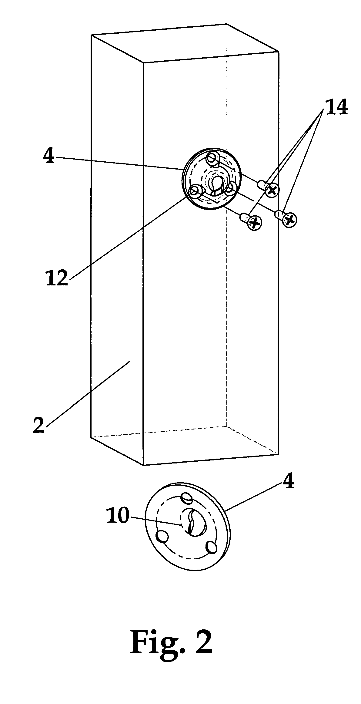
[0009]In one aspect, the present invention provides an assembly for easily attaching a wire to a rigid body, such as a free-standing bolt or a fixed surface of existing or new standard corner or end posts. As used herein, the term “wire” refers to unsheathed or sheathed wire or wire rope, of which 7×7, 1×19, and 7×19 are common constructions. The rigid body may be composed of any solid material (e.g., wood, plastic or metal.) The wire attachment assembly includes a collar component having a center aperture dimensioned to receive the wire, a threaded portion, and a tapered internal recess, a cylindrical member having a threaded end engaging the threaded portion of the collar, and a tapered wedge disposed between the collar and cylindrical member. The tapered wedge also has a center aperture dimensioned to receive the wire, but also has a groove extending along the length of the wedge such that when the cylindrical member and collar are screwed together, the tapered internal recess of the collar component compresses or crimps the tapered wedge tightly around the wire. The internal surface of the wedge may additionally have rough features to further secure the wire within the wedge.
[0024]waste of wire is minimized as the wire needs to be cut only after it has been unfurled from a reel or spool.

Problems solved by technology

Additionally, attaching such wooden balusters can be labor intensive and requires care while working with wood, due to the naturally occurring deformations and tendency to split.
Although most of the wire rope contemplated or used is stainless, the end fittings employed in such systems are either not stainless, and therefore corrode faster, or are stainless but require swaging by machine or manually with special hand swaging devices.
In most cases, such end fittings are not reusable, and often must be discarded if not installed correctly, resulting typically in a significant waste of wire rope as well.
In other systems, wire rope ends are formed into a loop and crimped, which is very unsightly.
A further significant disadvantage of existing railing systems is that average homeowners and even semi-skilled construction workers find installations to be difficult or impossible.
The knowledge required to correctly swage for sufficient breaking strength, and to choose the correct fittings and wire rope is usually possessed only by specialty industrial or marine (i.e., sailing, rigging) companies, which greatly limits their use in standard residential installations.
Furthermore, such specialized know-how makes stainless systems too expensive to be considered for standard houses, and impossible to mass market.
Other existing systems have even more pronounced limitations that become evident when railings are to be installed on stairs leading from or to a deck.

Method used


Image

  • Wire rope connectors and tensioners for deck railing systems
  • Wire rope connectors and tensioners for deck railing systems
  • Wire rope connectors and tensioners for deck railing systems

Examples


Embodiment Construction

[0033]The present invention provides a wire rope attachment means, tensioning means, and railing systems incorporating such means.

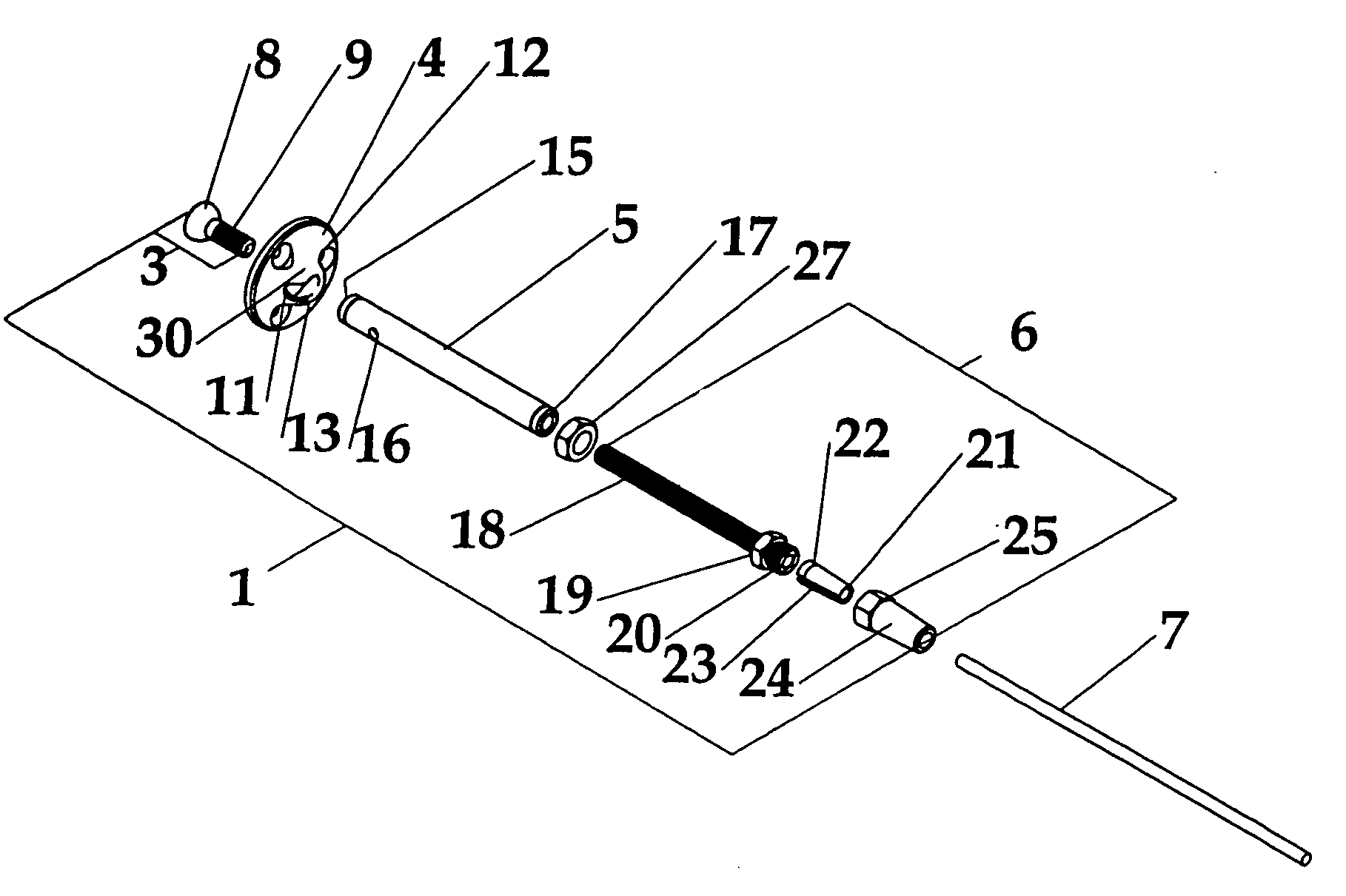
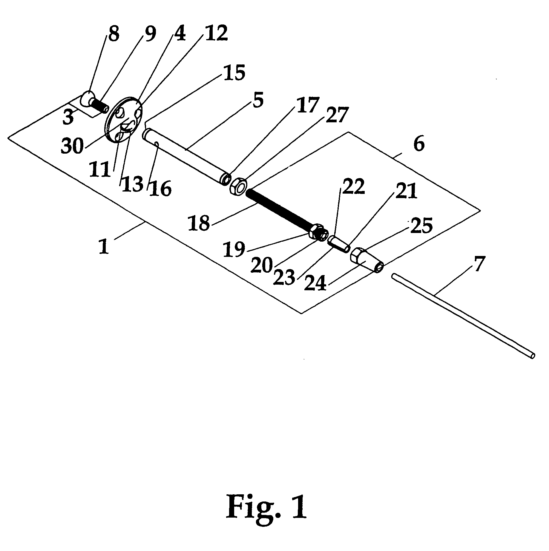
[0034]In a preferred embodiment, shown in FIG. 1 in an exploded perspective view, the present invention provides wire attachment assembly 6 that can be combined with a tensioning assembly to form a wire attachment and tensioning device 1. Each sub-assembly is preferably made entirely from stainless steel, or other corrosion resistant materials. In a preferred embodiment, the device is comprised of a threaded swivel 3, a mounting plate 4 having a center aperture 13, a tubular body 5 and the threaded wire rope attachment assembly 6 including a gripping wedge 22, collar 24 and rigid threaded stud 18.

[0035]The tensioning assembly is rotatably attachable to (or through) a support surface such as a railing post or a wall and includes a threaded end 17 to engage a threaded end of the stud 18 such that rotating the tensioning assembly adjusts the distance between...


PUM

PropertyMeasurementUnit
angleaaaaaaaaaa
distanceaaaaaaaaaa
lengthaaaaaaaaaa

Abstract

Wire attachment and / or tensioning assemblies are described. The ends of wires may be fitted with mateable collar and wedge components to allow the wire to be securely attached to a supporting structure such as, for example, the surface of a railing post. The wire attachment assembly may be rotatably attached to a tensioning device that enables wire tension adjustments without rotating the wire itself, thereby avoiding the need to adjust the opposing end of the wire.

Description

FIELD OF THE INVENTION[0001]The present invention relates to railing systems, and more particularly to easily configurable fixtures for attaching and / or tensioning cabling, rope or wire rope to surfaces such as those of railing corner posts.BACKGROUND OF THE INVENTION[0002]Traditional deck railings consist primarily of vertical balusters of wood or PVC in a variety of shapes, either set into specially shaped top and bottom rails, or attached to standard pieces of lumber. Most of the rail components are pressure-treated to resist rot and mildew but have to be cleaned, painted and / or sealed on a regular, often yearly basis, depending on the climate. Additionally, attaching such wooden balusters can be labor intensive and requires care while working with wood, due to the naturally occurring deformations and tendency to split.[0003]Some railing developers have endeavored to form railings employing horizontal wires or wire rope, spaced equally according to building regulations. Although ...

Claims


Application Information

Patent Timeline
Patent Type & Authority Patents(United States)
IPC IPC(8): B21F9/00B25B25/00B66F3/00E04F11/18E04H17/10F16G11/00F16G11/04F16G11/12
CPCE04F11/1834F16G11/00F16G11/12F16G11/04E04F2011/1882Y10T403/4908Y10T403/7052E04F11/1817E04F11/1859E04F2011/1819
Inventor STRIEBEL, ROMAN F.STRIEBEL, PATRICK A.
Owner SUNCOR STAINLESS
Learn More