Device for separating fluid mixtures

a fluid mixture and fluid technology, applied in sedimentation separation, multi-stage water/sewage treatment, feed/discharge of settling tanks, etc., can solve the problems of large devices, low discharge performance of oil and water separated from one another, and system downtime, so as to achieve optimum separation of components and low structural size , the effect of low cos

Inactive Publication Date: 2007-04-03
HYDAC FILTERTECHNIK GMBH
View PDF8 Cites 5 Cited by
  • Summary
  • Abstract
  • Description
  • Claims
  • Application Information

AI Technical Summary

Benefits of technology

[0004]Objects of the present invention are to provide an improved device for separating fluid mixtures, in particular for separating oil and water, with a low structural size, while retaining the advantages, allowing optimum separation of the components and operating economically favorably, in such a way that it can also be used at low and very low temperatures.
[0006]The heating means, preferably in the form of an electrically operated heating means, can be regulated in terms of its heating output, and can be tailored so that in a wide range of temperatures of the fluid mixture it can be handled appropriately in terms of separation within the separation device. Integration of the heating means into one sub-chamber of the vacuum tank causes only a small portion of the heat being released to the vicinity. This arrangement leads to improved efficiency and improves the rate of water removal.
[0007]In one preferred embodiment of the device of the present invention, one sub-chamber with the integrated heating means extends along the entire vacuum tank. The second sub-chamber with the packed bed encompasses the first sub-chamber. A third sub-chamber is coaxial to the second sub-chamber, and in the lengthwise direction of the vacuum tank likewise following the second sub-chamber encompasses the first sub-chamber. Division into different sub-chambers within the vacuum tank ensures that the heating means can occupy a large amount of space within the vacuum tank. This arrangement is advantageous in that the fluid mixture can then be routed over a very long section along the heating means. A correspondingly long residence time in the second sub-chamber is ensured by the packed bed so that a longer time interval is available for the separation or gas removal process. Rapid drainage of the separated liquid portions from the vacuum tank to the outside is then possible by the third sub-chamber with the packed bed.
[0008]In another preferred embodiment of the device of the present invention, a fourth sub-chamber which extends parallel to the first sub-chamber within the entire vacuum tank. A level monitoring means in the fourth sub-chamber provides information about the fill level of the vacuum tank relative to the respective liquid component. Preferably, the level monitoring means triggers a first delivery means such that when a given fill level boundary is not reached within the vacuum tank, the liquid component leaving the tank is passed onto the first sub-chamber with the heating means. Regardless of the fill level of the separation device and especially of the vacuum tank, it is consequently possible to conduct a continuing separation process which is especially independent of how much fluid mixture to be separated is being supplied from the outside to the separation device. In addition, more or less continuous operation proceeds favorably in terms of energy input. The fluid mixture which has already been separated can again be supplied to the actual separation device to improve the separation results in a further separation process. In this respect, fluid from which the air and water have been almost completely removed leaves the separation device for its further application.
[0010]In another preferred embodiment of the device of the present invention, the vacuum pump with its suction force adjoins the top of the vacuum tank. In the opposite direction, the fluid mixture flow takes place from top to bottom through the second sub-chamber with the packed bed. The arrangement of the vacuum pump which is the top arrangement in this respect and the countercurrent principle within the vacuum tank ensure a high separation rate. Moreover, streamlining is within the vacuum tank for the medium which is flowing at the time is achieved.
[0011]In another preferred embodiment of the device of the present invention, the vacuum tank can be connected to an air supply, preferably by a filter unit and an adjustable choke. In this way, purified air in definable amounts can be supplied to the vacuum tank to be able to set and specify the respective negative pressure in the vacuum tank in this way. Preferably, the fluid-carrying connection to the heating means and the parts of the fluid lines in the delivery means are each supplied by a hydraulic pump discharge into a common connecting piece. In this way, the free path and use of pipework can be reduced.

Problems solved by technology

This device is large.
This replacement leads to downtimes of the system.
With respect to the size of the system, the discharge performance on the oil and water which have been separated from one another is relatively low.
Especially under cold ambient conditions and for moreover cold fluid mixtures to be separated the water removal performance, the rate with which water removal takes place is insufficient.
Especially in applications at low and very low temperatures, the atomization means is fault-susceptible and is not especially well suited.

Method used


Image

  • Device for separating fluid mixtures
  • Device for separating fluid mixtures
  • Device for separating fluid mixtures

Examples


Embodiment Construction

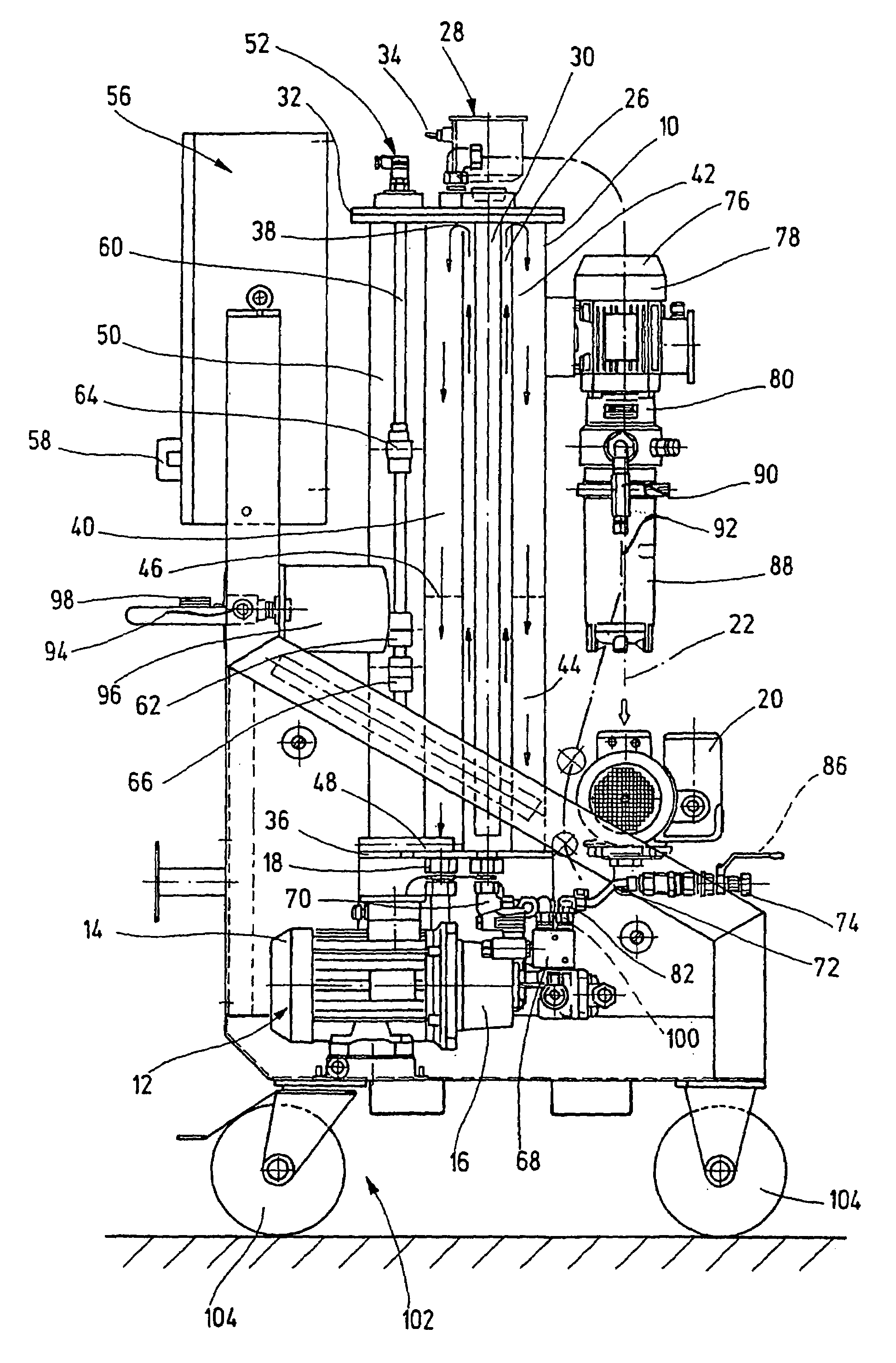
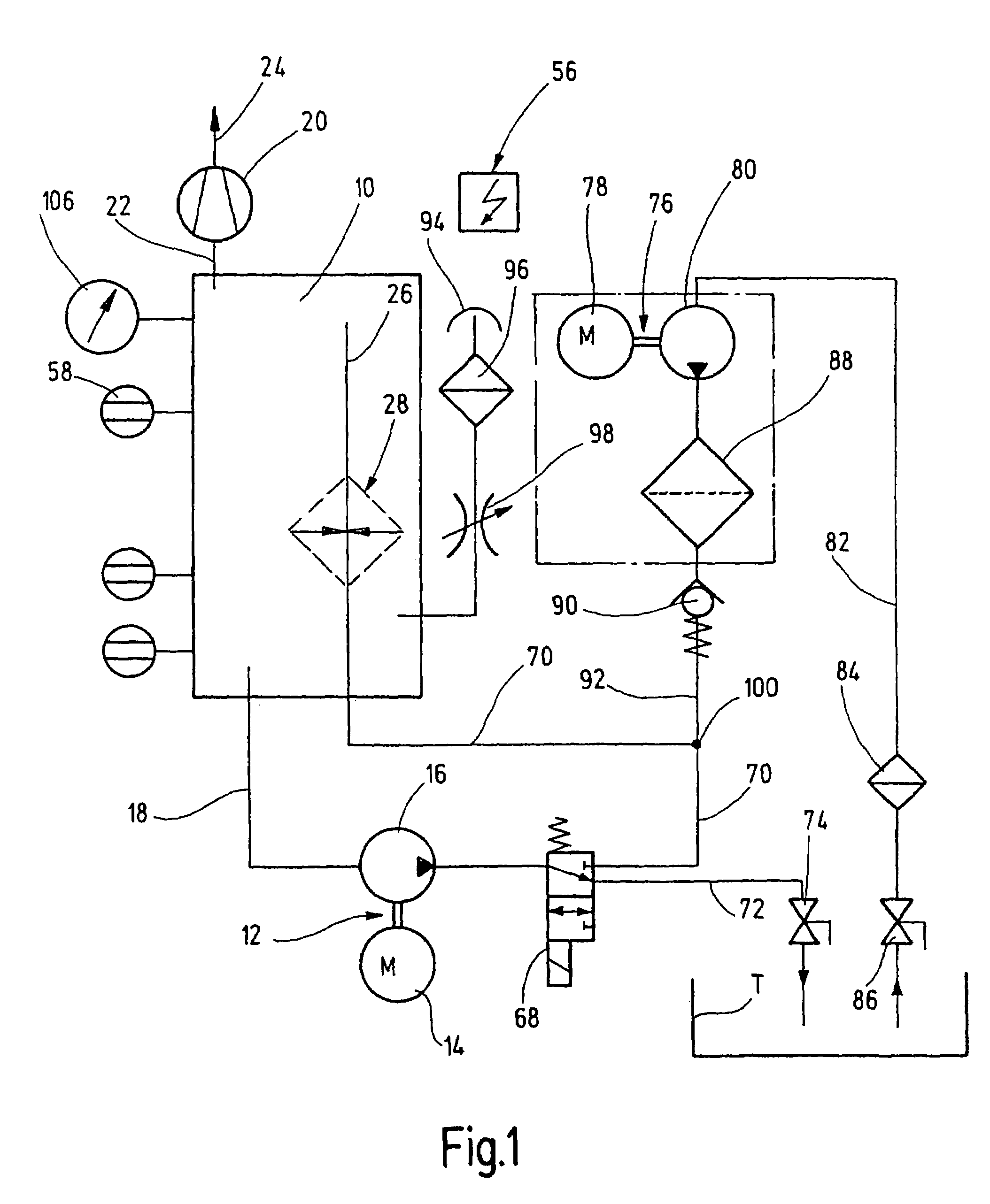
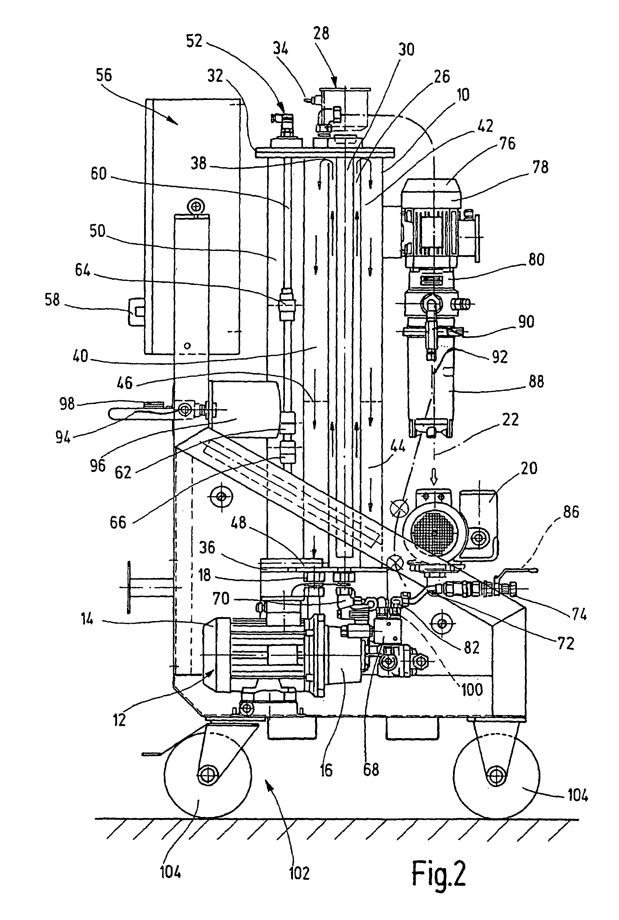
[0017]The device for separating fluid mixtures, especially water from oil, has a vacuum tank 10 into which the fluid mixture, e.g., in the form of an oil / water mixture, can be delivered. The liquid component of the fluid mixture, e.g., in the form of oil or another hydraulic medium, after completed separation, can be transported out of the vacuum tank 10 by a first delivery means 12. The first delivery means 12 has a hydraulic pump 16 driven by an electric motor 14. For the respective removal, the first delivery or conveyor means 12 is connected by a pipeline 18 to carry fluid from the bottom of the vacuum tank 10. Furthermore, the separation device has a vacuum pump 20 which is conventional for applications and which is connected by a connecting line 22 (shown only partially in FIG. 2) in the upper part of the vacuum tank 10 to the vacuum pump for carrying fluid. The output 24 of the vacuum pump 20 can be connected to a receiving tank which is not detailed or to another liquid drai...


PUM

PropertyMeasurementUnit
temperatureaaaaaaaaaa
absolute pressureaaaaaaaaaa
pressureaaaaaaaaaa

Abstract

A device for separating fluid mixtures, in particular for separating water from oil, includes a vacuum container (10) with several sub-chambers (26, 44, 40). At least one liquid constituent of the fluid mixture can be transported from the vacuum container after separation, by a transport device (12). The other constituents can be extracted from the vacuum container (10) in the form of gas and / or steam, using a vacuum pump (20). One of the sub-chambers (26) of the vacuum container (10) houses a heating device (28, 30), which heats the fluid mixture. The fluid mixture is guided into an additional sub-chamber (40), and is separated into its constituents by traversing a packed bed. Even cold and consequently viscous fluid mixtures can be supplied, due to the heating device, for separation inside the aforementioned vacuum container.

Description

FIELD OF THE INVENTION[0001]The present invention relates to a device for separating fluid mixtures, in particular for separating water from oil, comprising a vacuum tank with several sub-chambers. At least one liquid component of the fluid mixture can be transported out of the vacuum tank after separation by a delivery means. The other components can be extracted from the vacuum tank in gas and / or vapor form by a vacuum pump.BACKGROUND OF THE INVENTION[0002]In a non-generic device for separating an oil / water mixture disclosed in EP 0 148 444 A2, a pre-separation space is provided in which first the coarser components of the oil are separated from the mixture. The mixture precleaned in this way is then delivered to a coalescence chamber containing a plurality of coalescing bodies of an oleophilic plastic and being lighter than water. Extremely fine oil particles also settle on the oleophilic, specifically large surfaces of these bodies, flow together on the bodies and rise as larger...

Claims


Application Information

Patent Timeline
Patent Type & Authority Patents(United States)
IPC IPC(8): C02F1/02B01D1/06B01D19/00B01D24/12B01D3/00B01D35/01B01D36/00C10G33/00B01D1/00B01D3/10B01D3/34B01D17/00
CPCB01D1/0017B01D3/10B01D3/34B01D17/005B01D17/02
Inventor HERGES, KNUTBUSCH, ANDREAS
Owner HYDAC FILTERTECHNIK GMBH
Why Eureka
Try Eureka