Wireless tailgate lights

Inactive Publication Date: 2007-04-03
MIXON RONALD
View PDF15 Cites 15 Cited by
  • Summary
  • Abstract
  • Description
  • Claims
  • Application Information

AI Technical Summary

Benefits of technology

[0017]It is desirable to make the device as lightweight as possible and allow the receiver to be mounted either with magnets, tie straps or clamps to the trailer for easy installation and removal.
[0018]It is an object of this device to

Problems solved by technology

Unfortunately, when one of these wires breaks the electric

Method used


Image

  • Wireless tailgate lights
  • Wireless tailgate lights
  • Wireless tailgate lights

Examples


Embodiment Construction

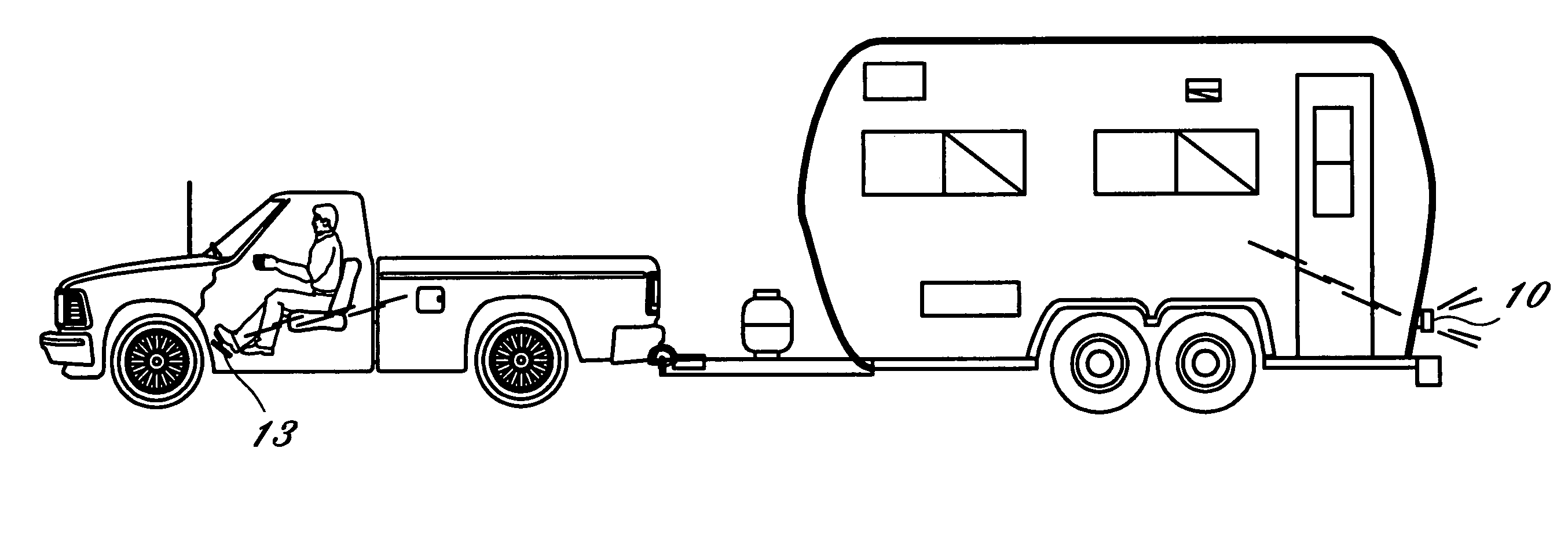
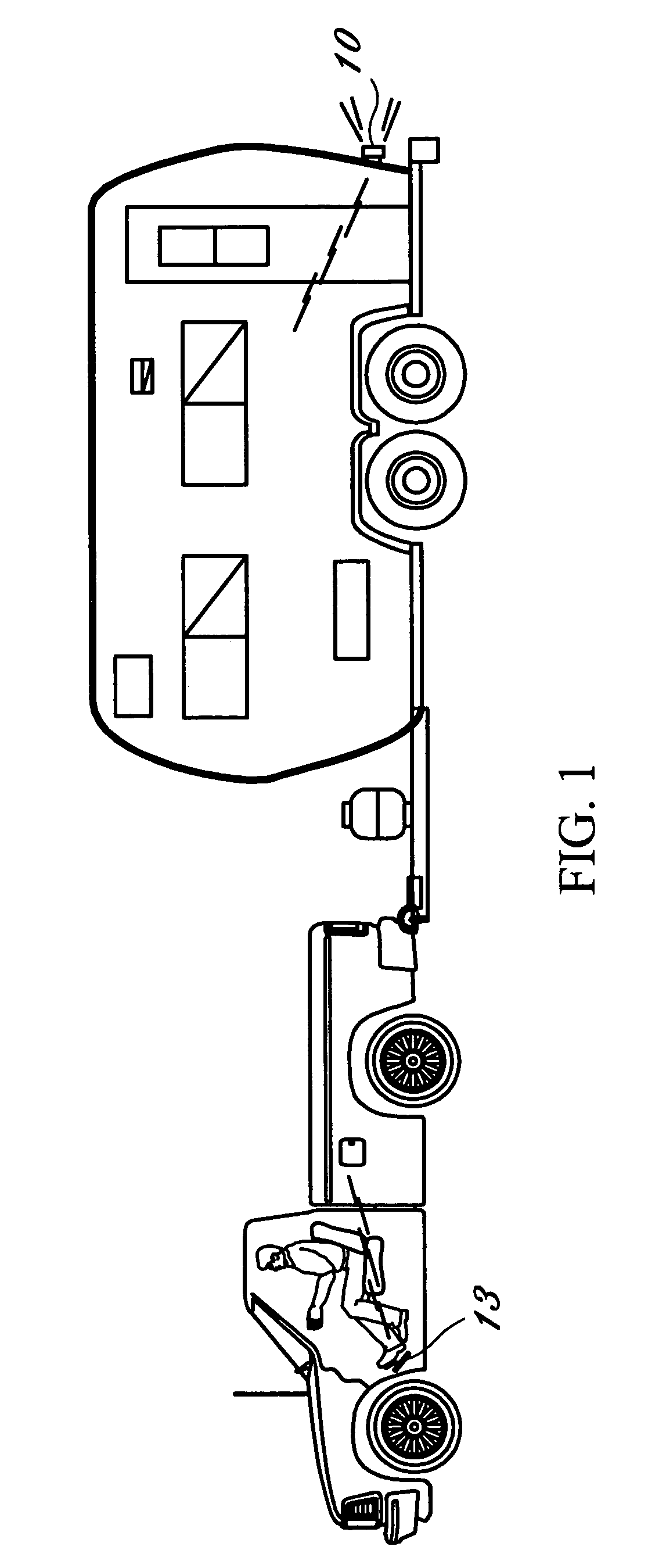
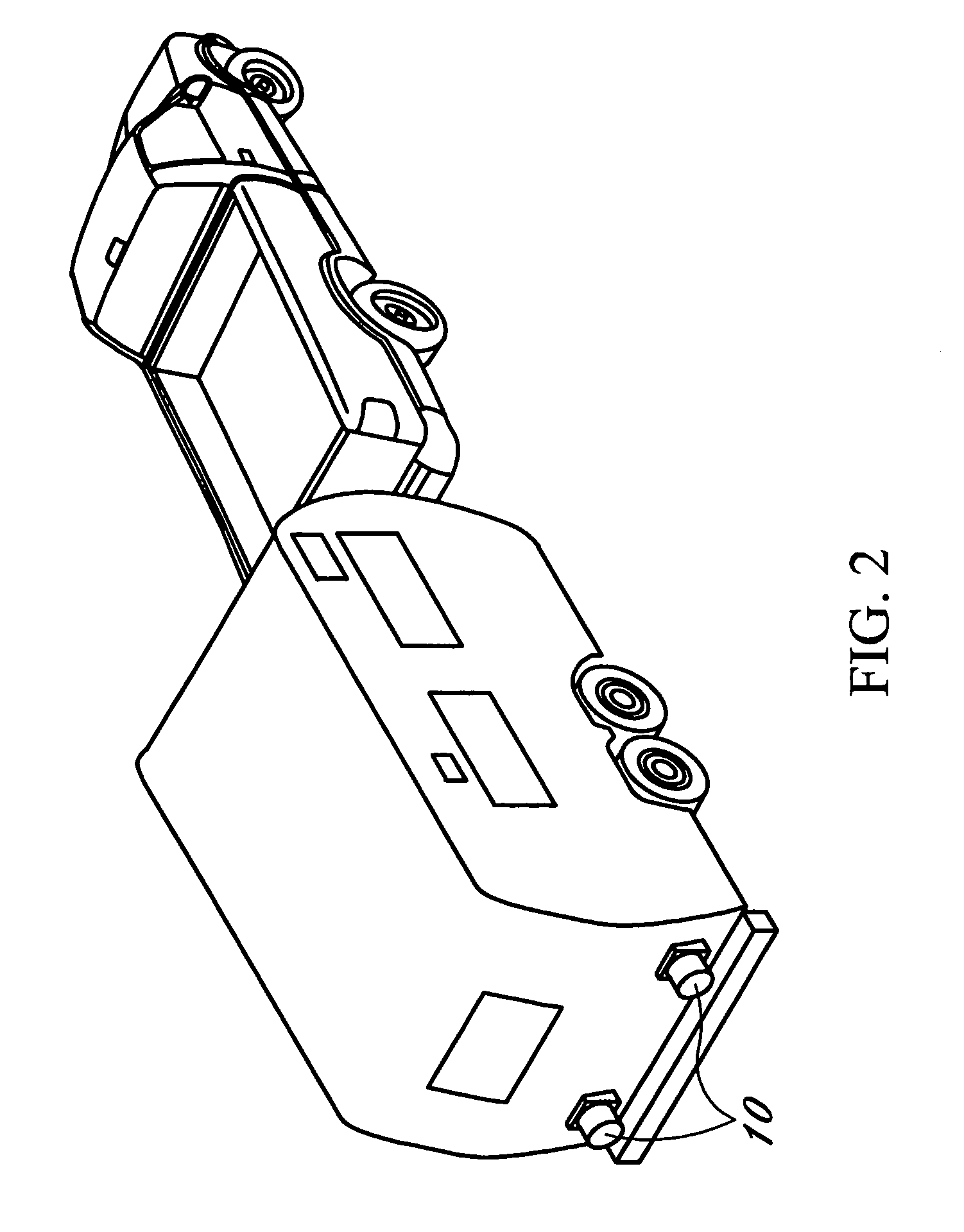
[0027]This device is a set of portable brake lights 10, which are operated using a transmitter 20 and a receiver 12. The device is comprised of a sleeve 13, which contains a series of contact points 17. When the brake is depressed the contact points cause the transmitter 20 to emit a radio frequency signal to a receiver 12, which is integrated into the structure, which houses the brake lights 10. FIGS. 1, 2, 3

[0028]Within the sleeve 13 is a plurality of pressure sensitive contacts 17, which are placed around the brake pedal 11 of the vehicle in such a manner that they are depressed against the brake pedal when the operator of the vehicle operates the brake. FIGS. 4, 5, 7

[0029]When the pedal is depressed and the contact points 17 are depressed a radio signal is emitted by the transmitter 20 and sent to the receiver 12, which is contained with the taillight 10. FIGS. 3, 6, 8

[0030]Unlike conventional taillight systems the device and signal are not dependent upon any wiring because it i...


PUM


Abstract

This device is a wireless tailgate braking and turn signal System, which will temporarily enable a driver of a vehicle to have taillights and/or a blinker system for emergency situations. This would insure road safety in all types of conditions, both in terms of extremes in temperature and inclement weather.

Description

CROSS REFERENCES TO RELATED APPLICATIONS[0001]Not ApplicableSTATEMENT REGARDING FEDERALLY SPONSORED RESEARCH[0002]Not ApplicableREFERENCE TO APPENDIX[0003]Not ApplicableBACKGROUND OF THE INVENTION[0004]A. Field of the Invention[0005]This device addresses the need for roadside safety and in particular portable tailgate lights for emergency situations.[0006]B. Prior Art[0007]The invention relates to the need for temporary taillights with the capability of a blinker system. This is designed to be temporary or to be used only in emergency situations.[0008]A representative patent of this particular technology is Seaburg, U.S. Pat. No. 4,859,982, which is a wireless tailgate system. However, integrating the system into the tailgate circuitry of the vehicle operates the Seaburg patent. Although the need to be satisfied is the same, the operation of the current device is substantially different from Seaburg.[0009]In this current application a sleeve is inserted over the brake pedal. Contain...

Claims


Application Information

Patent Timeline
IPC IPC(8): B60Q1/30
CPCB60Q1/305B60Q2900/30
Inventor MIXON, RONALD
Owner MIXON RONALD
Why Eureka
Try Eureka