Twist drill and method for producing a twist drill which method includes forming a flute of a twist drill

a twist drill and drill bit technology, which is applied in the direction of twist drills, manufacturing tools, wood boring tools, etc., can solve the problems of drill breaking off, comparatively weak cutting wedges in the vicinity, and high drilling forces

Inactive Publication Date: 2007-04-10
KENNAMETAL INC
View PDF11 Cites 40 Cited by
  • Summary
  • Abstract
  • Description
  • Claims
  • Application Information

AI Technical Summary

Benefits of technology

[0009]The object of the invention is to

Problems solved by technology

In the vicinity of the main cutting edges, however, the positive secondary cutting angle has the disadvantage that the cutting wedge is comparatively weak in the vicinity of the face edge on account of its acute-angle geometry.
However, precisely in the vicinity of the face edge is where very high forces occur during drilling.
Thus at this point in particular there is a danger that the drill will break off.
A further disadvantage is that the chip thrown off is curved, which requires an addit

Method used


Image

  • Twist drill and method for producing a twist drill which method includes forming a flute of a twist drill
  • Twist drill and method for producing a twist drill which method includes forming a flute of a twist drill
  • Twist drill and method for producing a twist drill which method includes forming a flute of a twist drill

Examples


Embodiment Construction

[0054]In the figures, identical parts or parts that have an equivalent effect are identified by the same reference numbers.

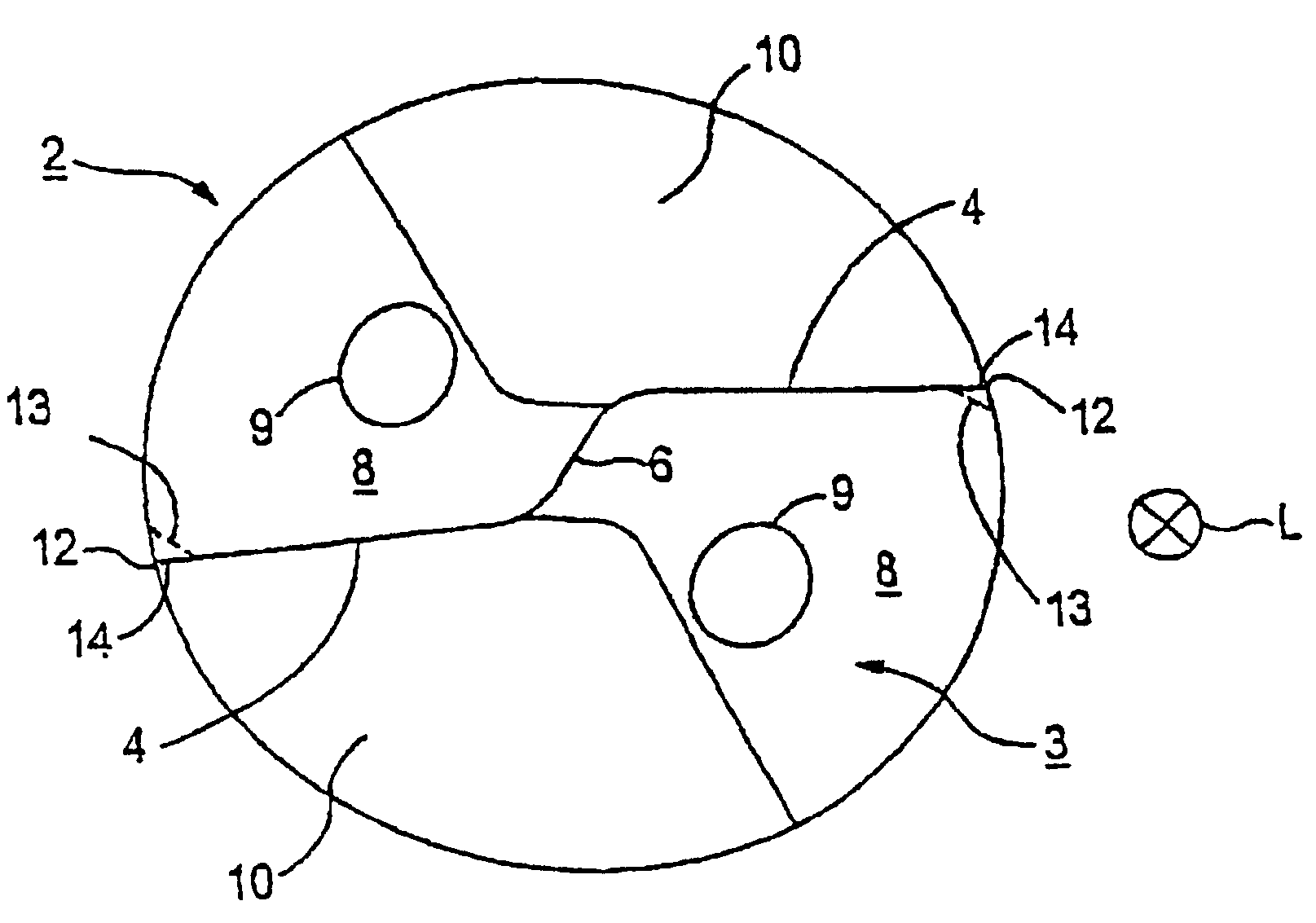
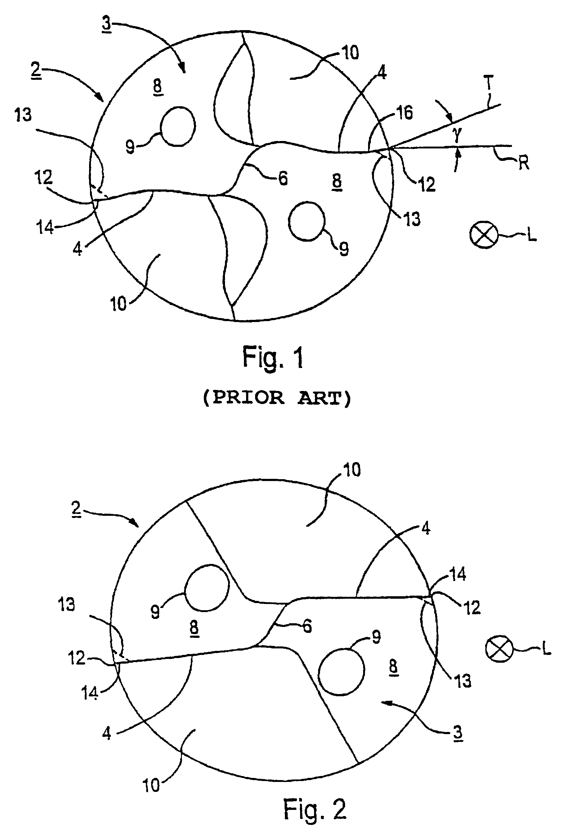
[0055]A conventional twist drill 2 illustrated in FIG. 1 and called a drill for short, has on the face end of its drill bit 3 two main cutting edges 4 which are connected to each other by a chisel edge 6. The main cutting edges 4 and the chisel edge 6 are curved in approximately the shape of an “S”. Adjacent to each of the two main cutting edges 4 is a main clearance face or surface 8, each of which transitions into a flute 10.

[0056]The two main cutting edges or lips 4 run in approximately the radial direction of the drill 2. The main clearance faces 8 each have coolant boring 9, by means of which the drill 2 can be cooled during the drilling process. Adjacent to each of the main cutting edges 4 on the end-side, thereby forming a face edge 12, is a secondary cutting edge 14, which run in the longitudinal direction L of the drill, i.e. into the plane of the paper...


PUM

PropertyMeasurementUnit
Angleaaaaaaaaaa
Angleaaaaaaaaaa
Angleaaaaaaaaaa

Abstract

A twist drill and method for producing is provided. The cutting edge structure has a first portion at the drill tip portion and a second portion disposed away from the drill tip portion. The flute wall extends further into the land structure at the second portion of the cutting edge structure than at the tip portion to provide a greater amount of drill material at the tip portion than at the second portion of the cutting edge structure. The flute wall extends further into the land structure at the second portion of the cutting edge structure than at the tip portion to provide a greater flute volume per length at the second portion of the cutting edge structure than at the drill tip portion.

Description

CONTINUING APPLICATION DATA[0001]This application is a Continuation-in-Part application of International Application No. PCT / EP01 / 05751, filed on May 19, 2001, and claiming priority from German Patent Application No. DE 100 27 544.3, filed on Jun. 2, 2000. International Application No. PCT / EP01 / 05751 was pending as of the filing date of this application. The United States was an elected state in International Application No. PCT / EP01 / 05751.BACKGROUND OF THE INVENTION[0002]1. Field of the Invention[0003]This invention relates to a twist drill and method for producing a twist drill which method includes forming a flute of a twist drill.[0004]2. Background Information[0005]On a conventional bit for a twist drill, the generally two main cutting edges are curved via the chisel edge so that they run into one another in the shape of an “S”. Adjacent to each of the main cutting edges is a main clearance face which transitions into a flute which is realized so that it runs in a spiral shape ...

Claims


Application Information

Patent Timeline
IPC IPC(8): B23B51/02B24B3/24B23B51/00B24B19/04
CPCB23B51/02B24B19/04B23B2251/406Y10T408/9097Y10T408/909Y10T408/455
Inventor MUHLFRIEDEL, DIETERBORSCHERT, BERNHARDSCHWAGERL, JURGEN
Owner KENNAMETAL INC
Why Eureka
Try Eureka