Stationary ring assembly for a gas turbine

a technology of gas turbine and ring assembly, which is applied in the direction of machines/engines, liquid fuel engines, lighting and heating apparatus, etc., can solve the problems of significant air leakage in the slot, particularly detrimental to the cooling of the segment, and the efficiency of the turbin

Active Publication Date: 2007-04-10
SN DETUDE & DE CONSTR DE MOTEURS DAVIATION S N E C M A
View PDF7 Cites 29 Cited by
  • Summary
  • Abstract
  • Description
  • Claims
  • Application Information

AI Technical Summary

Benefits of technology

[0012]Another advantage of the invention resides in the fact that these air leaks are eliminated without adding auxiliary parts (of the angle-bar type) that are detrimental to the weight of the assembly, without requiring the slots and the sealing strips to be modified significantly, and without leading to maintenance problems.
[0013]The stationary ring assembly may constitute a high-pressure turbine ring for a turbomachine. Under such circumstances, each ring segment may include, in each side face, two axial slots disposed towards its inner and its outer walls, and in which axial strips are received, and two radial slots disposed towards its upstream and its downstream walls, and in which radial strips are received.
[0014]The stationary ring assembly may also constitute a spacer on which the high-pressure turbine ring of the turbomachine is fastened. Under such circumstances, each spacer segment may include, in each side face, one axial slot in which an axial strip is received, and at least three radial slots, two of which are disposed towards its upstream and its downstream walls, and in which radial strips are received.
[0015]The present invention also provides a segment for a gas-turbine stationary ring assembly as defined above.

Problems solved by technology

However, in practice, it should be observed that such an arrangement of the slots generates significant air leaks at the junctions between the axial and radial slots.
Such leaks are particularly detrimental to the cooling of the segments and to the efficiency of the turbine.

Method used


Image

  • Stationary ring assembly for a gas turbine
  • Stationary ring assembly for a gas turbine
  • Stationary ring assembly for a gas turbine

Examples


Embodiment Construction

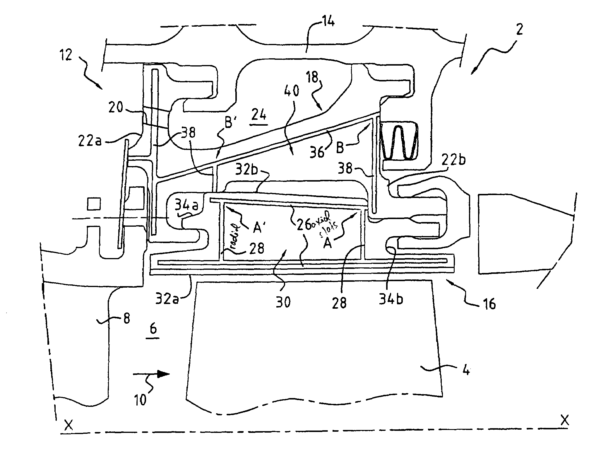
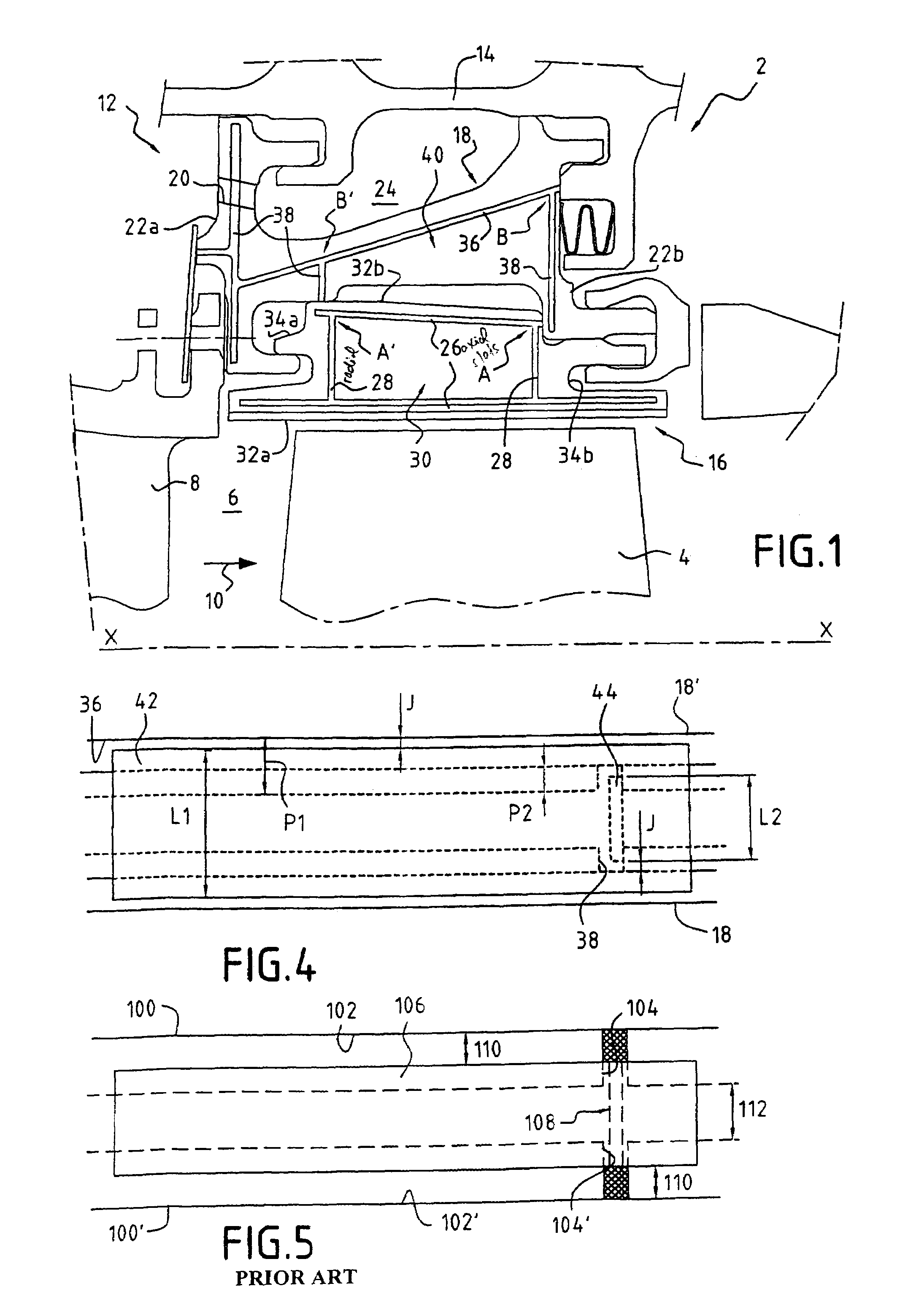
[0022]With reference to FIG. 1, a turbomachine high-pressure turbine 2 of longitudinal axis X—X is made up in particular of a plurality of moving blades 4 forming a rotor and disposed in the annular flow-path 6 of a flow of hot gas coming from the combustion chamber (not shown). A plurality of stationary blades 8 forming a high-pressure nozzle are also disposed in the flow path 6, upstream from the moving blades 4 relative to the flow direction 10 of the gas.

[0023]The moving blades 4 are surrounded by a stationary ring assembly 12 forming a shroud. The stationary ring assembly is made up of a turbine ring fastened onto a casing 14 of the turbine by means of a plurality of spacer segments 18. More particularly, the turbine ring is made up of a plurality of ring segments 16 joined end to end. By way of example, there can be two ring segments 16 mounted on a single spacer segment 18.

[0024]The stationary ring assembly 12 defined in this way includes an air-flow circuit making it possibl...


PUM


Abstract

A stationary ring assembly forming a rotor shroud for a gas turbine including a plurality of segments having adjacent side faces that are placed end to end with sealing means interposed therebetween. The sealing means include at least one axial sealing strip and at least one radial sealing strip respectively received in axial slots and in radial slots formed facing one another in the adjacent side faces of the segments. At least one end of each radial slot opens out into the corresponding axial slot, each axial slot of a segment presents a depth that is greater than the depth of the corresponding radial slot, and the axial sealing strip presents a width that is greater than the width of the radial strip.

Description

BACKGROUND OF THE INVENTION[0001]The present invention relates to the general field of stationary ring assemblies for gas turbines. It relates more particularly to stationary ring assemblies for turbomachine high-pressure turbines when the assemblies are of the type constituted by a plurality of segments joined end to end with sealing strips interposed therebetween.[0002]In a gas turbine, e.g. a turbomachine high-pressure turbine, the rotor-forming moving blades are surrounded by a stationary ring assembly forming a shroud. The stationary ring assembly thus defines one of the walls of the flow path for the hot gas coming from the combustion chamber of the turbomachine and passing through the turbine.[0003]The stationary ring assembly is made up of a turbine ring fastened onto the casing of the turbine by means of a spacer. In general, the ring and the spacer of such a stationary ring assembly are in the form of sectors, i.e. they are each made up of a plurality of segments joined en...

Claims


Application Information

Patent Timeline
Patent Type & Authority Patents(United States)
IPC IPC(8): F01D11/14F01D9/04F01D11/00F01D25/00F02C7/28
CPCF01D11/005
Inventor GENDRAUD, ALAINROUSSIN-MOYNIER, DELPHINE
Owner SN DETUDE & DE CONSTR DE MOTEURS DAVIATION S N E C M A
Why Eureka
Try Eureka