Fan with central intake

a technology of central intake and fan, which is applied in the direction of machines/engines, stators, liquid fuel engines, etc., can solve the problems of heat at the center of the radiator, the central processor will be shutdown, and the effect of reducing the stagnation zone produced by the fan, removing heat from an article being cooled, and enhancing heat dissipation effectively

Inactive Publication Date: 2007-04-10
ASIA VITAL COMPONENTS SHENZHEN CO LTD
View PDF7 Cites 12 Cited by
  • Summary
  • Abstract
  • Description
  • Claims
  • Application Information

AI Technical Summary

Benefits of technology

[0012]A primary object of the present invention is to provide a fan with central intake in which a flow route is disposed at the center of the fan to reduce a stagnation zone produced by the fan and so as to remove heat from an article being cooled and enhance heat dissipation effectively.
[0013]Another object of the present invention is to provide a fan with central intake in which a flow route is disposed at the center of the fan to remove beat from a joining part and a driving device so as to enhance operation efficiency of the fan.

Problems solved by technology

Otherwise, the central processor will be shutdown resulting from overheat if there is no excellent heat dissipation device.
But, the main unit of a computer provides a limited space for the fan being located so that how to promote function of heat dissipation with a fan in proper size becomes relatively significant.
As a result, heat at the center of the radiator 16 is incapable of being dissipated and the heat dissipation capability becomes lowered.
Obviously, the conventional fan does not provide a way to discharge the heat sources and it is the reason of the conventional fan provides unfavorable effect of heat dissipation.

Method used


Image

  • Fan with central intake
  • Fan with central intake
  • Fan with central intake

Examples


first embodiment

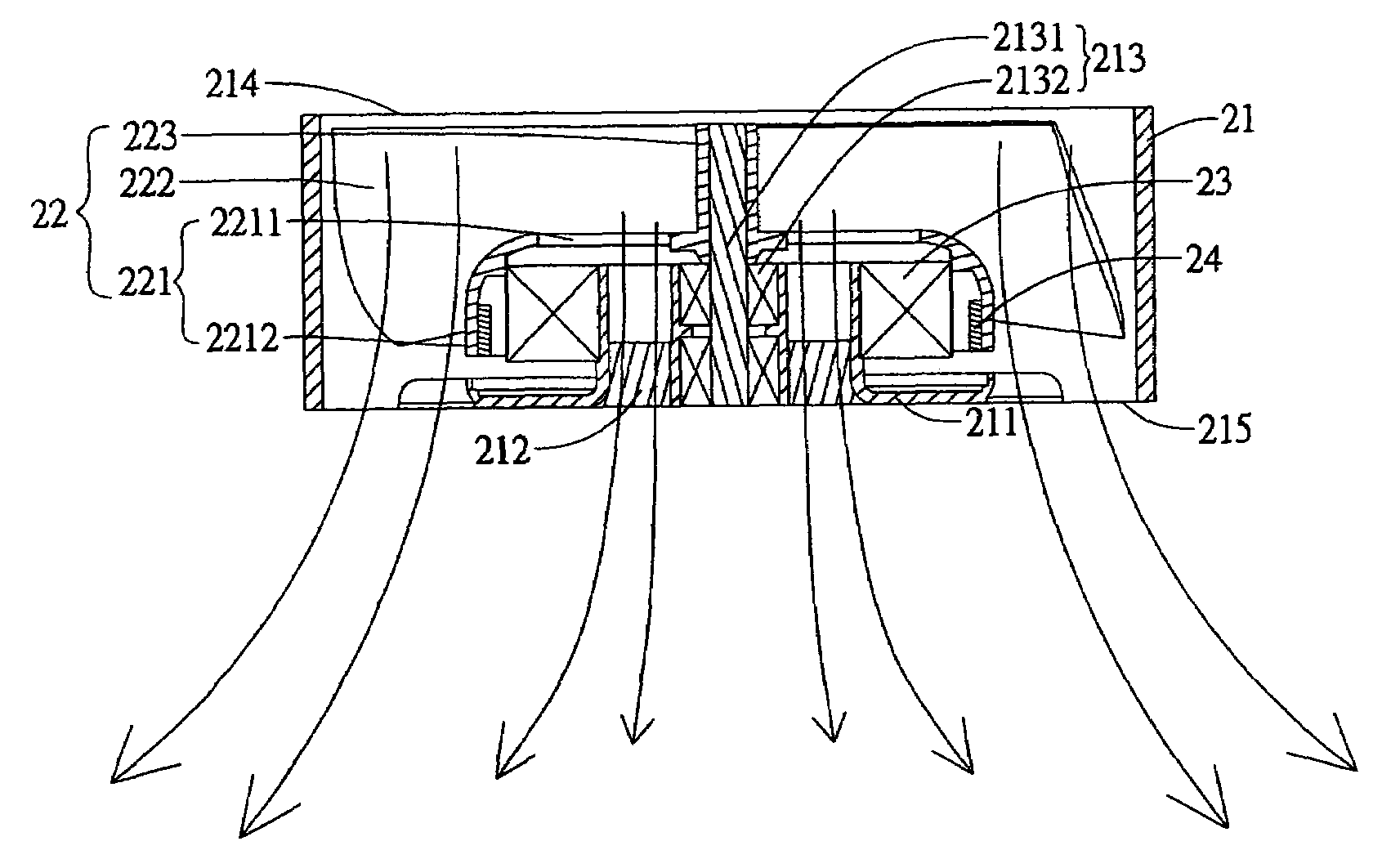
[0048]Referring to FIGS. 6 and 7, a fan with central intake according to the present invention comprises a fan frame 21 and a fan wheel 22. The fan frame 21 provides an inlet 214 and an outlet 215. A hub seat 211 is located at the outlet 215 with an annular spacing 212 being disposed in the hub seat 211 between the inner circumferential wall surface and a joining part 213, which is disposed at the center of the hub seat fixedly attached to the hub seat with four radial joining bars for fluid being capable of moving through. The joining part 213 is cylindrical for supporting two bearings 2132 and a spindle 2131 rotatably fits with the bearings 2132 and an end of the spindle 2131 extends to the inlet 214 as an extending section. A motor stator 23 of a driving device, which is a fan motor, fits with the hub seat 211. The fan wheel 22 has a hub 221 with a short U shaped cross section and the hub 221 has an open side and a hub wall 2212 with a circular opening 2211 opposite to the open s...

third embodiment

[0059]Referring to FIGS. 30 and 31, the annular spacing 412 of the hub seat 411 in the third embodiment can be diverged downward from the top or converged downward from the top to control outgoing fluid and extend flowing range or control the fluid flowing toward rear side of the joining part 413 so as to allow the fluid at the rear side of the joining part 413 to keep moving and prevent from creating the stagnation zone.

[0060]Referring to FIGS. 32 and 33, the blades 422 of the fan wheel 42 in the third embodiment is provided to incline rightward. Under this circumstance, the fluid enters the hub seat 411 from the side of the inlet and flows toward the radiator 46 via the side of the outlet so that the same effect and function can be reached as well.


PUM


Abstract

A fan with central intake comprises a fan frame, a fan wheel and a fan motor. The fan frame provides a hub seat with an annular spacing for fluid flowing through and a joining part at the center of the hub seat for supporting the bearings. The fan wheel is received in the fan frame and provides a hub with an open side and a hollow side with a circular opening. The annular spacing associated with the circular opening constitutes a central flow route for admitting fluid to pass through such that heat from the central area of a radiator under the fan can be dissipated efficiently.

Description

BACKGROUND OF THE INVENTION[0001]1. Field of the Invention[0002]The present invention is related to a fan with central intake and particularly to a fan frame with a fan wheel for dissipating heat in an electronic product.[0003]2. Brief Description of the Related Art[0004]Due to development of electronic technology, the central processor is operated with high time pulse to satisfy requirement of high executing speed. However, the central processor with high speed of data processing accompanies with much more heat generation too.[0005]In order to dissipate the heat, it is necessary to provide a heat dissipation device. Otherwise, the central processor will be shutdown resulting from overheat if there is no excellent heat dissipation device.[0006]Currently, the most popularly used heat dissipation device is the cooling fan because of its low cost. This is why the manufacturers are interested in developing and researching the fan.[0007]But, the main unit of a computer provides a limited...

Claims


Application Information

Patent Timeline
Patent Type & Authority Patents(United States)
IPC IPC(8): F04D29/32
CPCF04D25/0613F04D29/582
Inventor LIU, WEN-HAOCHOU, CHU-HSIEN
Owner ASIA VITAL COMPONENTS SHENZHEN CO LTD
Why Eureka
Try Eureka