Air vent for a ventilation system

a ventilation system and air vent technology, applied in ventilation systems, vehicle cleaning, heating types, etc., can solve the problems of uneven appearance of the outlet surface, inability to cover the guide elements on the outlet surface with a grid or the like, and inability to uniformly cover the guide elements on the outlet surfa

Inactive Publication Date: 2007-04-10
TRW AUTOMOTIVE ELECTRONICS & COMPONENTS GMBH & CO KG
View PDF12 Cites 46 Cited by
  • Summary
  • Abstract
  • Description
  • Claims
  • Application Information

AI Technical Summary

Benefits of technology

[0014]In a preferred embodiment, the perforated wall area is formed by a fine-meshed grid. This arrangement gives the visible front of the air vent a uniform appearance.

Problems solved by technology

The appearance of the outlet surface is characterized by the position of the guide elements and is not uniform.
A covering of the guide elements on the outlet surface with a grid or the like is not possible since the orienting effect would be lost with such a covering.
With these, the outlet surface can have a uniform appearance, but no orienting effect is possible, so that outflow devices with a diffusing effect are installed in the vehicle in addition to those with an orienting effect when both modes of air distribution are to be provided.

Method used


Image

  • Air vent for a ventilation system
  • Air vent for a ventilation system
  • Air vent for a ventilation system

Examples


Embodiment Construction

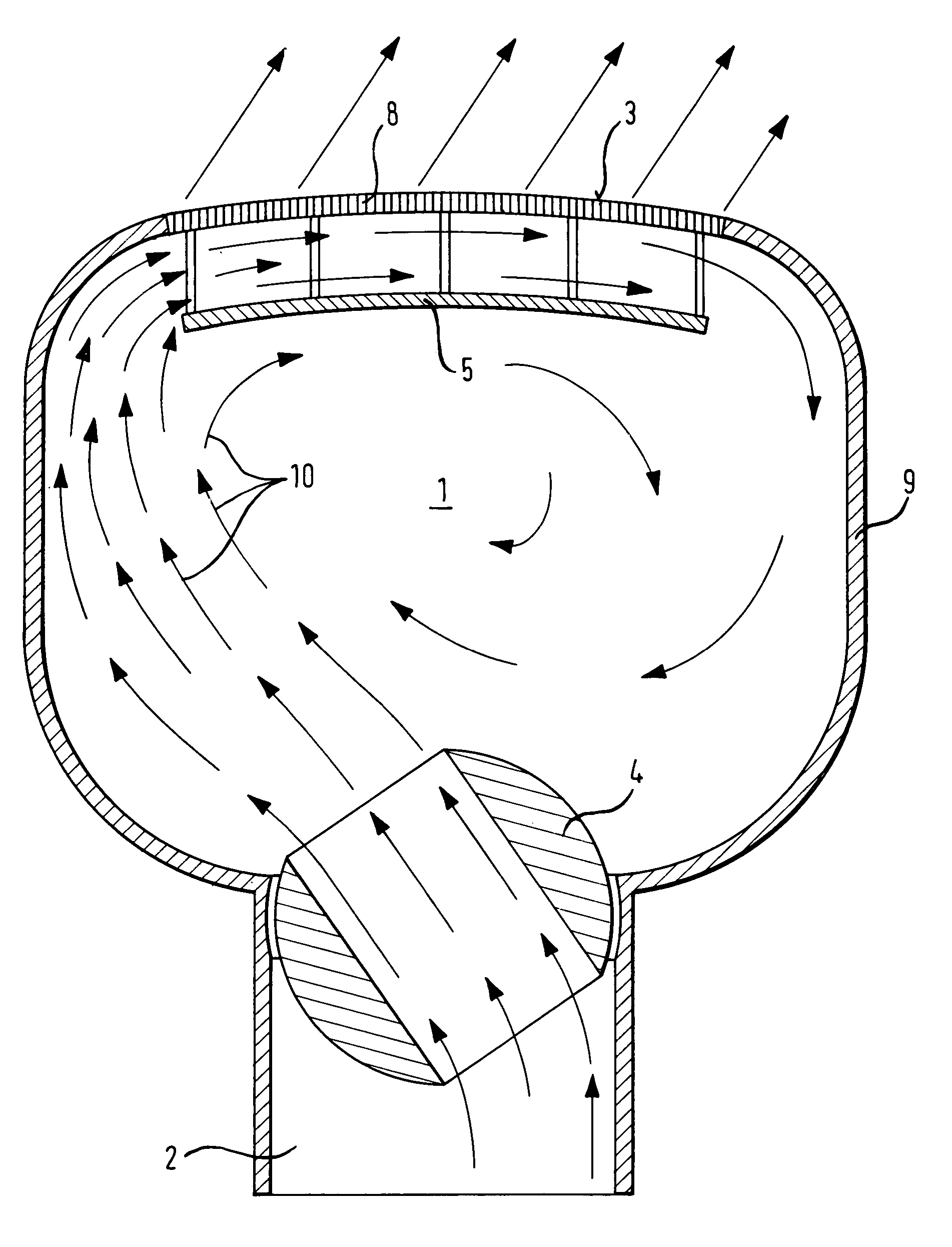
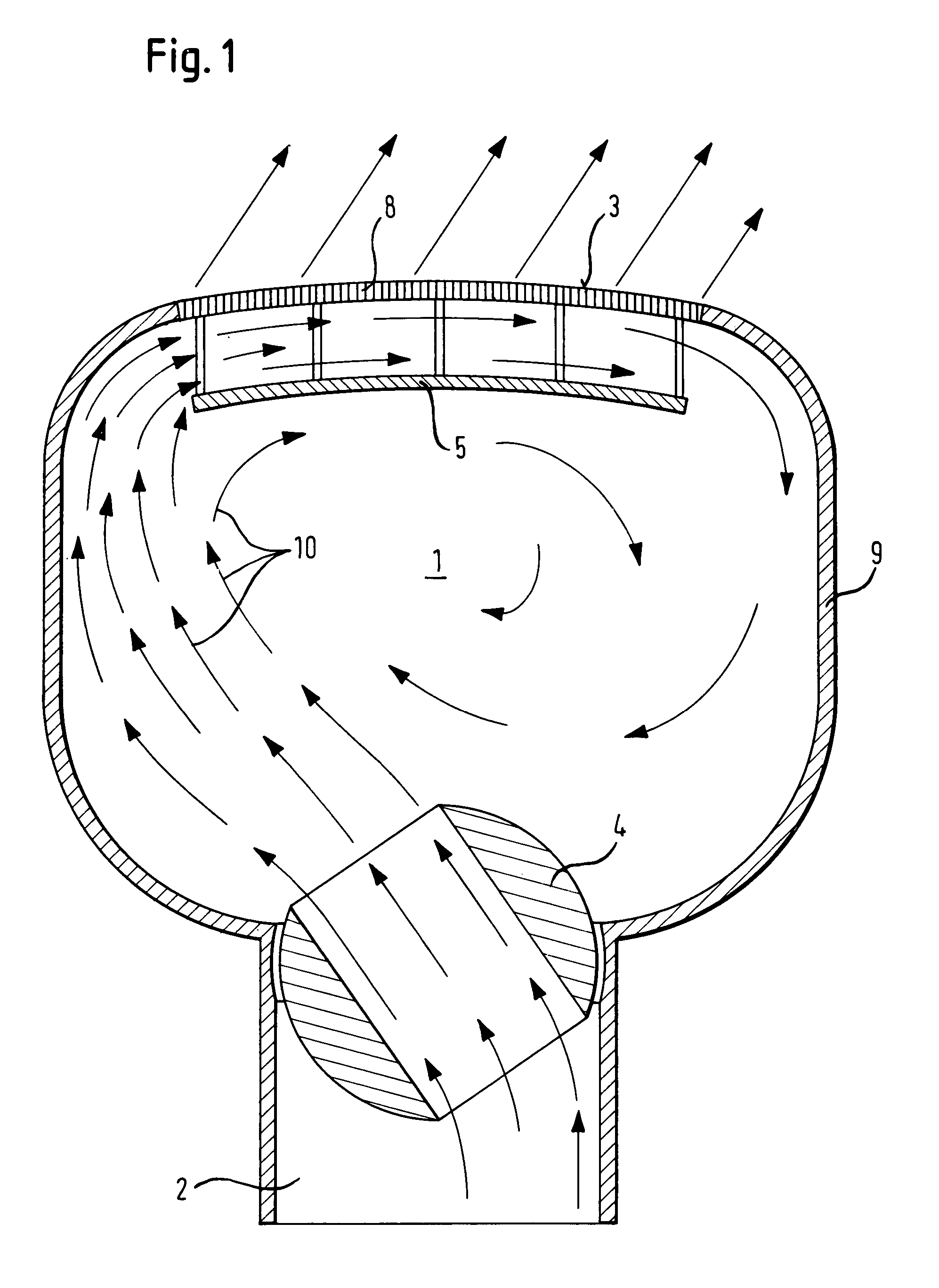
[0023]The air vent has a generally rectangular frame 10 with to pairs of opposed frame sections. The longer ones 10a, 10b of opposed frame sections are spanned by a plurality of ribs 11. The frame with the ribs 11 is injection-molded from a plastic material. An antenna is incorporated in the frame. specifically, the antenna has a generally T-shaped metallic body 12 with a first branch 12a that spans the frame sections 10a, 10b centrally of the frame and a second branch 12b perpendicular to the first branch 12a and extending along frame section 12b.

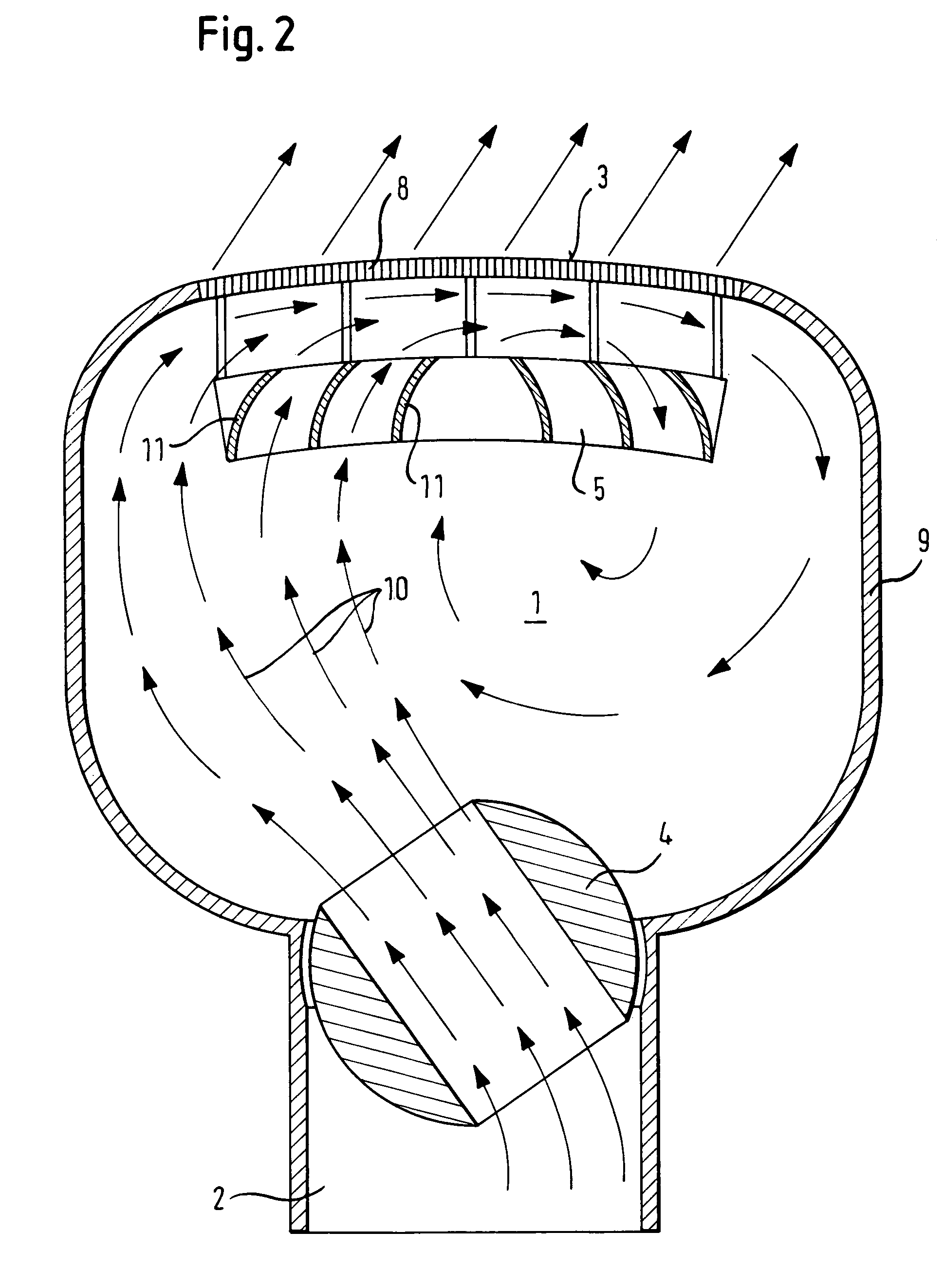
[0024]FIG. 2 shows an embodiment that is slightly modified with respect to that of FIG. 1. Air guide 5 includes here a set of curved baffle members 11 at fixed positions upstream of perforated wall area 3. A partial air flow inside circulation chamber 1 is imparted with a circular movement determined by the position of movable air deflection member 4. Compared to the embodiment of FIG. 1, the air flow in FIG. 2, indicated by arrows 10, is...


PUM


Abstract

An air vent for a ventilation system in a vehicle is disclosed that has an air circulation chamber (1) defined by a housing (9) that has a generally bulged shape. An inflow duct (2) is connected to this housing and opens into the circulation chamber (1), the housing having a perforated wall area (3). An air stream, in use, enters the circulation chamber (1) through inflow duct (2), circulates through the air circulation chamber and exits through the perforated wall area. The air vent further comprises a movable air deflection member disposed to deflect the air stream transversely to an axial direction of the inflow duct.

Description

FIELD OF INVENTION[0001]The invention relates to an air vent for a ventilation system in a vehicle.BACKGROUND OF THE INVENTION[0002]With the known ventilation systems, the air emerges through outflow vents having air guide elements such as vanes or rotating cages that are usually adjustable and near the outlet surface. The appearance of the outlet surface is characterized by the position of the guide elements and is not uniform. A covering of the guide elements on the outlet surface with a grid or the like is not possible since the orienting effect would be lost with such a covering.[0003]Air vents are also known that have a diffusing effect. With these, the outlet surface can have a uniform appearance, but no orienting effect is possible, so that outflow devices with a diffusing effect are installed in the vehicle in addition to those with an orienting effect when both modes of air distribution are to be provided.[0004]DE 197 21 831 A1 describes an air outflow device for the interi...

Claims


Application Information

Patent Timeline
Patent Type & Authority Patents(United States)
IPC IPC(8): B60H1/34B60H1/26
CPCB60H1/3414E04B1/90E04C2/365E04F15/206
Inventor DEMERATH, MICHAELBITTCHER, MARKUS
Owner TRW AUTOMOTIVE ELECTRONICS & COMPONENTS GMBH & CO KG
Why Eureka
Try Eureka