

DC-to-DC converter
a converter and converter technology, applied in the direction of electric variable regulation, process and machine control, instruments, etc., can solve the problems of unsuitable applications for converters in the uk, and achieve the effect of simple and low-cost circuitry
- Summary
- Abstract
- Description
- Claims
- Application Information
AI Technical Summary
Benefits of technology
Problems solved by technology
Method used
Image

Examples
first embodiment
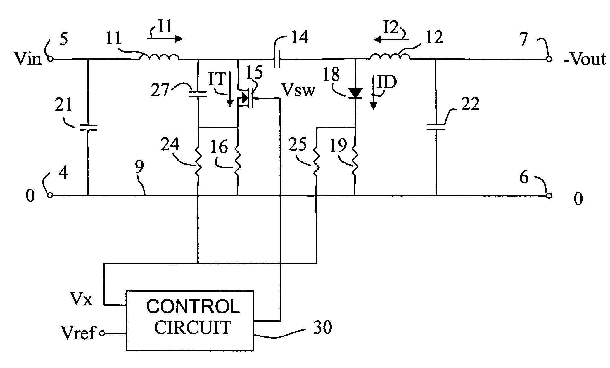
[0016]the DC-to-DC converter shown in FIG. 1 comprises a first input terminal 4, a second input terminal 5, a first output terminal 6, and a second output terminal 7. Said first terminals 4 and 6 are connected to a common conductor 9. A series circuit of an input inductor 11, an output inductor 12, and a capacitor 14 between said inductors 11 and 12 is connected across the second input terminal 5 and the second output terminal 7. A power FET 15 is connected to a node of the input inductor 11 and the capacitor 14 and in series with a resistor 16 to the common conductor 9. A diode 18 is connected to a node of the output inductor 12 and the capacitor 14 and in series with a resistor 19 to the common conductor 9. Buffer or equalizing capacitors 21 and 22 are connected across the input terminals 4, 5 and the output terminals 6, 7, respectively.
[0017]Resistors 16 and 19 have small values and serve to develop a voltage across them in dependence on a current IT or ID flowing through them, r...
second embodiment
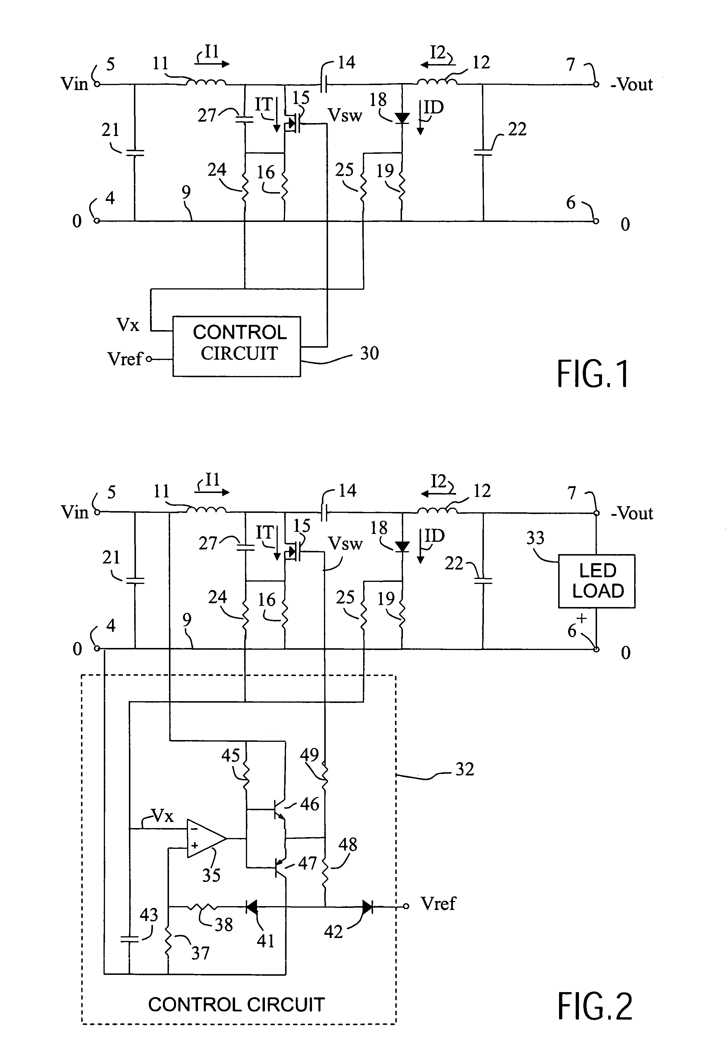
[0027]the converter according to the invention shown in FIG. 2 comprises a basic arrangement of the control circuit 30 which shows a much faster response to changes in a difference between said compared signals.
[0028]The second embodiment shown in FIG. 2 comprises a control circuit 32 instead of control circuit 30 of FIG. 1. In addition, a LED load 33 is shown connected to the output terminals 6 and 7. Alternatively, a load such as the LED load 33 may be connected to the second input terminal 5 and second output terminal 7, with the positive terminal connected to the second input terminal 5 in the case of a LED load. With such an arrangement, a voltage across the load will be Vin+Vout. With identical voltages across a LED load in both cases, less power has to be converted in the latter case.
[0029]Control circuit 32 is a simple hysteresis controller. Control circuit 32 comprises a comparator 35. A positive input of comparator 35 is connected to the common conductor 9 via a resistor 3...
PUM
 Abstract
Description
Claims
Application Information