
Power converter

a power converter and converter technology, applied in the direction of ac network voltage adjustment, transmission system, efficient power electronics conversion, etc., can solve the problems of high cost of components, high cost of switching relatively high peak high current at a high frequency, etc., to reduce flicker, improve power quality, and simple power supply

Active Publication Date: 2014-01-21
POWER RES ELECTRONICS BV
View PDF14 Cites 5 Cited by
  • Summary
  • Abstract
  • Description
  • Claims
  • Application Information

AI Technical Summary

Benefits of technology

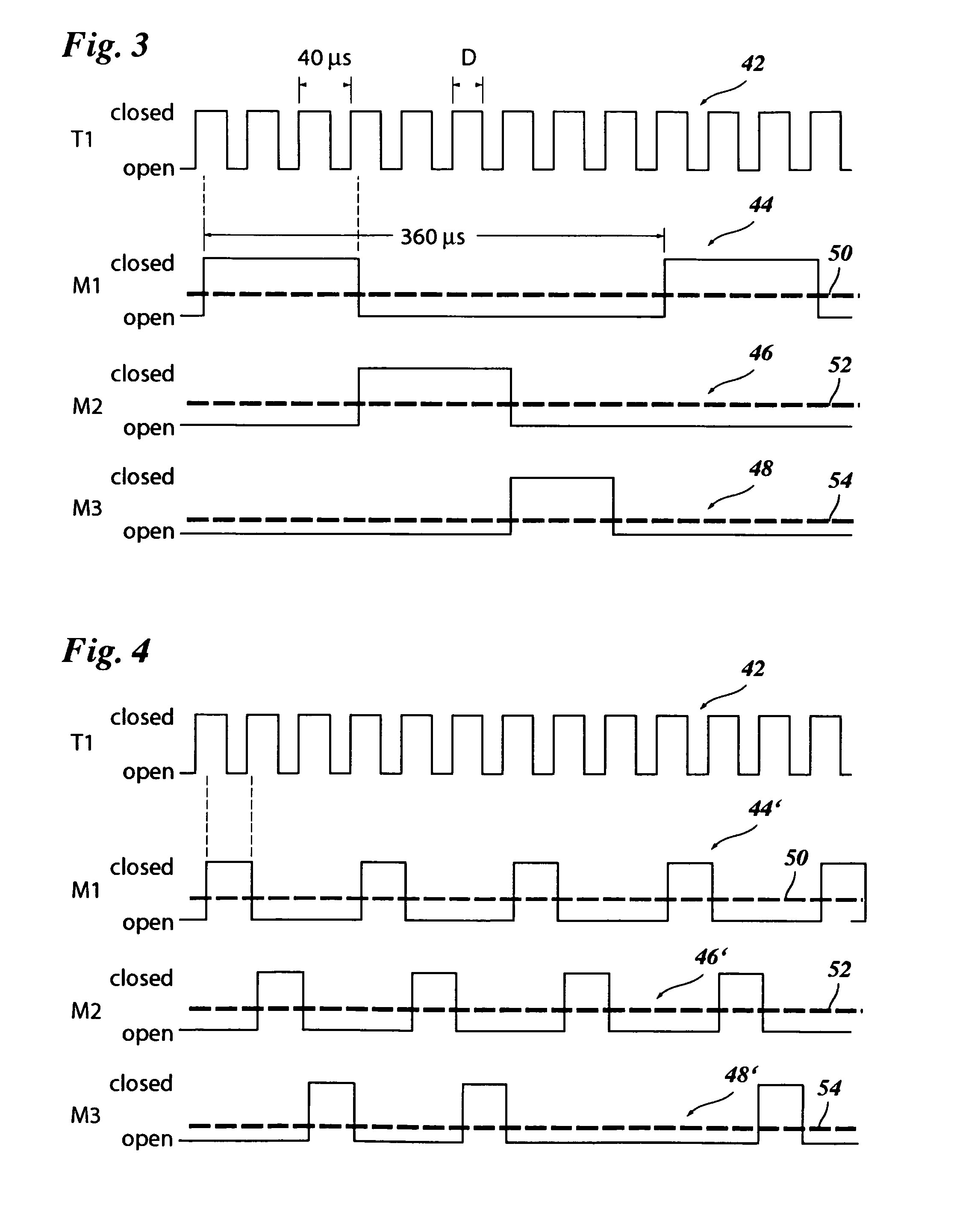
The invention provides a power converter with low complexity and low costs that allows for individual power control of multiple load circuits. The invention uses a multiplexer to switch between the load circuits, resulting in an average power delivered to each output circuit that can be finely controlled. The use of a single inductive element and a single switch reduces costs and efficiency. The multiplexer also reduces flicker and improves power quality on the grid.

Problems solved by technology

Since the inductive element is a custom-designed, hand-made element, this component is expensive, especially when it also has to provide safety isolation between the grid and the outputs.
Switching relatively high peak high currents at a high frequency (in order to keep the dimensions of the inductive element small) is also expensive.

Method used


Image

  • Power converter
  • Power converter
  • Power converter

Examples


Embodiment Construction

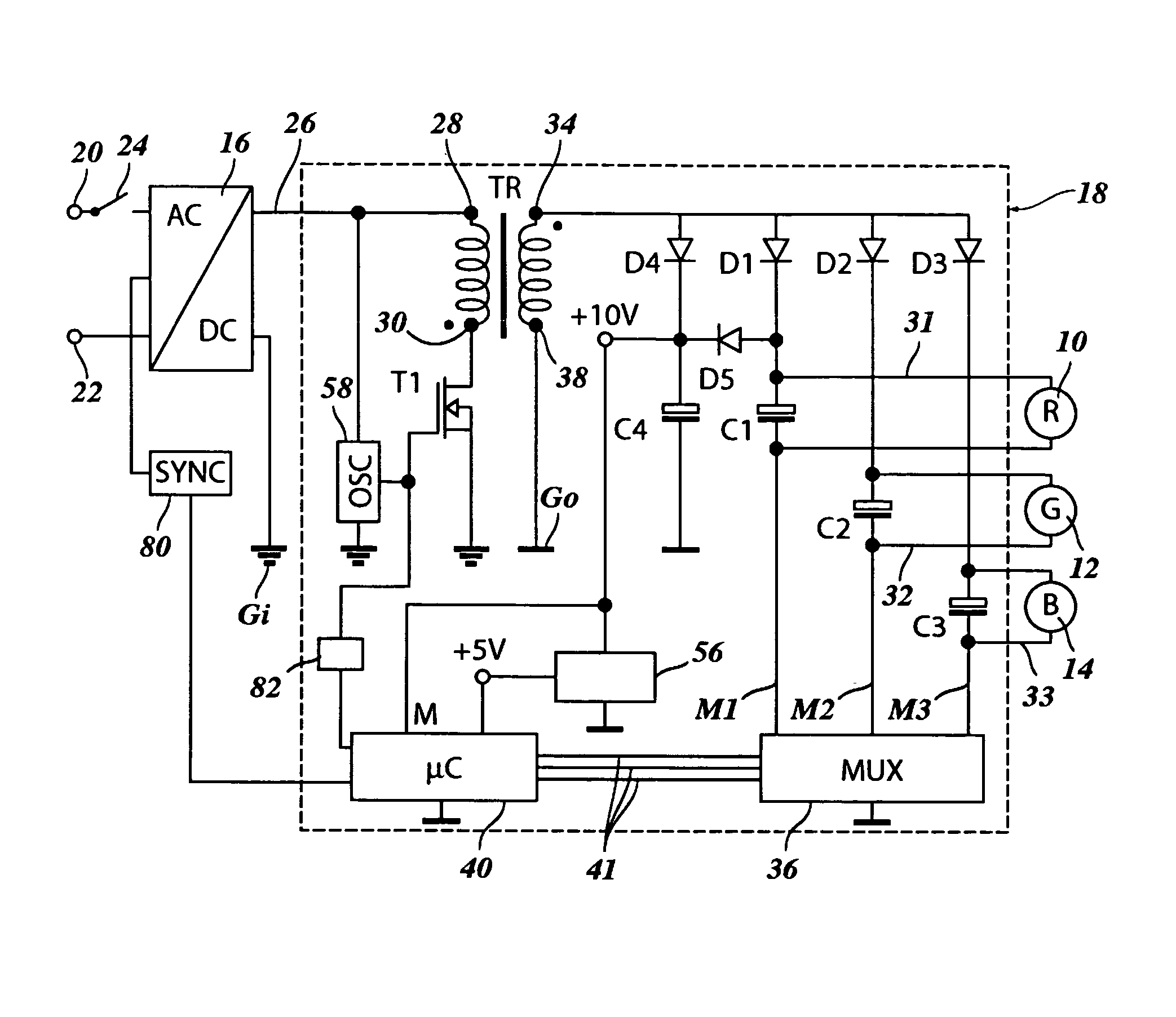
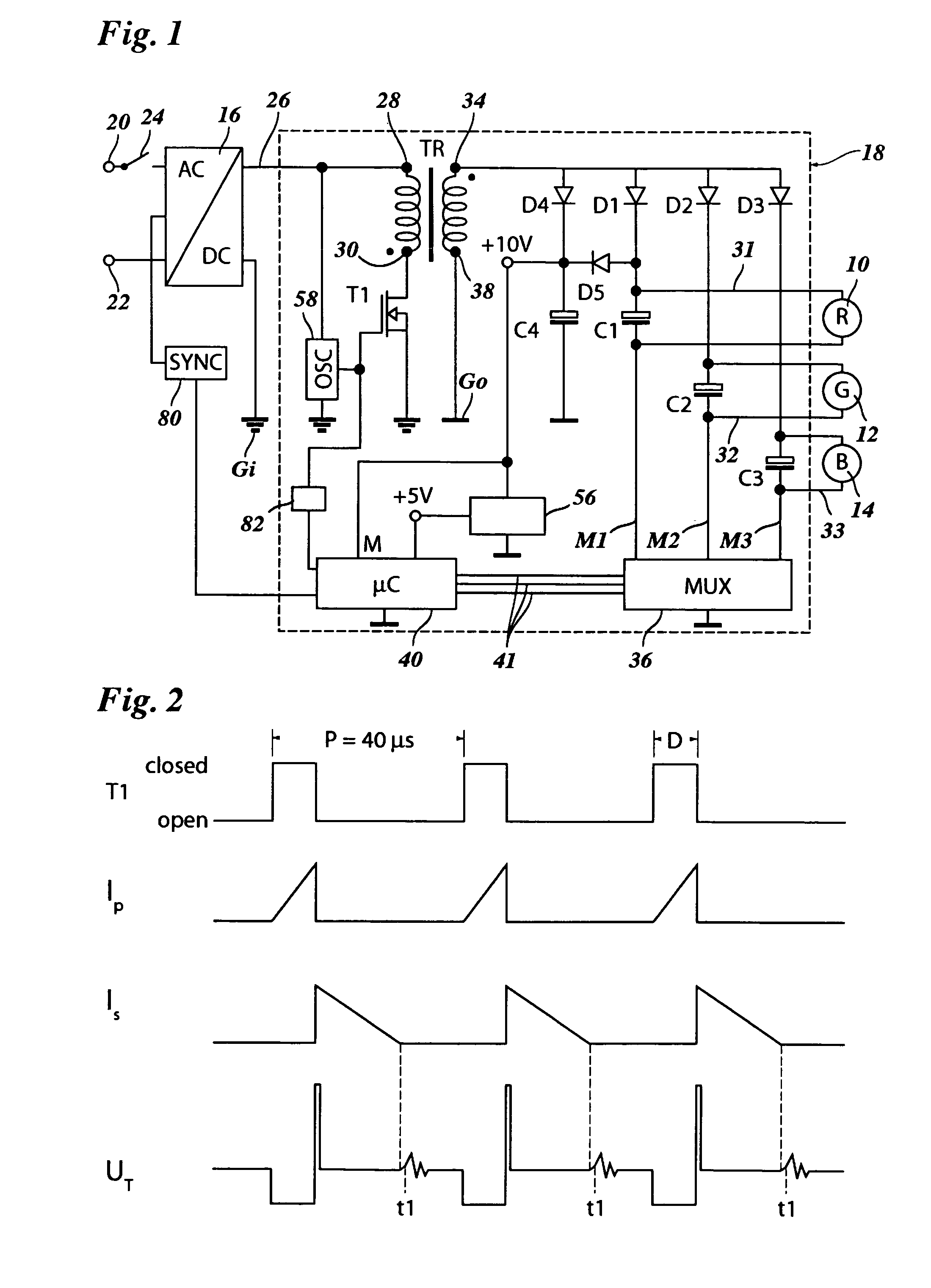
[0021]FIG. 1 illustrates an LED driver serving as a power supply for three LEDs 10, 12, 14 in the colors red (R), green (G) and blue (B). While only a single LED per color has been shown in the drawing, each of these single LEDs may be replaced by a network comprising a series and / or parallel connection of several LEDs of the same color.

[0022]The LED driver comprises an AC / DC converter 16 and a DC / DC power converter 18. The AC / DC converter 16 has an input side connected to terminals 20, 22 of a 230 V / 50 Hz power grid, for example, via a manually operated switch 24, and it further comprises an output side connected to a DC input 26 of the DC / DC converter 18.

[0023]The DC input 26 of the DC / DC converter 18 is connected to a first primary terminal 28 of an inductive element, in this case a transformer TR, and a second primary terminal 30 of that transformer is grounded via a switch T1, which, when closed, closes the primary circuit of the transformer. The switch T1 may for example be an...


PUM


Abstract

A power converter includes a DC input (26) connected to an inductive element (TR), a switch (T1) arranged to interrupt the inductive current cyclically with a predetermined cycle period, a plurality of load circuits (31, 32, 33), and a multiplexer (36) having a plurality of parallel channels (M1, M2, M3) between first and second output terminals (34, 38) of the inductive element (TR), wherein each channel includes one of the load circuits (31, 32, 33), and the multiplexer is adapted to make the channels conductive sequentially and periodically, and the multiplexer has a switching period that is a multiple of the predetermined cycle period of the switch (T1).

Description

BACKGROUND OF THE INVENTION[0001]The invention relates to a power converter comprising a DC input connected to an inductive element, a switch arranged to interrupt the inductive current cyclically with a predetermined cycle period, a plurality of load circuits, and a multiplexer having a plurality of parallel channels between first and second output terminals of the inductive element, wherein each channel includes one of the load circuits, and the multiplexer is adapted to make the channels conductive sequentially and periodically.[0002]More particularly, the invention relates to a power converter that can be used as an LED driver, especially for high luminance LEDs for illumination purposes.[0003]LED illumination devices, e.g. devices that may be connected to the power grid by being screwed into a socket like a conventional light bulb, may be equipped with white LEDs or with combinations of colored LEDs, e.g. in the basic colors red, green and blue (RGB). Combinations of colored LE...

Claims


Application Information

Patent Timeline
Patent Type & Authority Patents(United States)
IPC IPC(8): H02J3/14H05B44/00
CPCH02M3/33561H05B33/0827H02M3/1588Y02B70/1466Y10T307/484Y10T307/406H05B45/46Y02B70/10
Inventor WANNER, JANKARDOLUS, MENNOSCHIJFFELEN, JOS H.
Owner POWER RES ELECTRONICS BV
Learn More