Electronic anti-theft system

an electronic anti-theft and electronic technology, applied in anti-theft devices, program control, instruments, etc., can solve the problems of inconvenient operation, and inability to unlock doors, etc., to achieve the effect of quick unlocked, easy operation, and rapid unlocking

Inactive Publication Date: 2007-04-10
SIEMENS AG
View PDF15 Cites 16 Cited by
  • Summary
  • Abstract
  • Description
  • Claims
  • Application Information

AI Technical Summary

Benefits of technology

[0008]To avoid this and reduce the response time for passive access, the cryptological data which is exchanged between the key and the control device can be exchanged at very high data transmission speeds with a specified query strategy. This ensures that the doors are unlocked and can therefore be opened directly after an access authorization request. However this is frequently inadequate to reduce the response time, so that the doors are also unlocked within the corresponding response time, thereby avoided repeated activation of the door handle. A further problem arises in that, as transmission speeds increase, the energy consumption required for an access authorization request also increases, which ideally should be avoided.
[0010]The object of the present invention is to reduce the response time for the mechanical unlocking of a lock device in an anti-theft system.
[0027]The particular advantage is that the motor vehicle doors can now be opened very quickly so that in the case of a keyless passive access authorization system, multiple activation of the door handles to open the doors is not required or occurs a lot less. Access to the motor vehicle is thus configured in a more user-friendly manner. Since the alarm system has not yet been disarmed at this point in time, a high security standard remains guaranteed despite the premature opening of the doors.
[0030]The particular advantage in the case of keyless driver authorization systems is that the steering wheel lock can be very quickly unlocked, since only the first data communication (authentication) has to be awaited here. The second data communication, by means of which the immobilizer is deactivated, is effected in parallel with this unlocking process. In contrast to the mechanical unlocking process of the steering wheel lock, deactivation of the immobilizer is effected electronically and can be effected extremely quickly in the event of positive identification of an authorized vehicle user. In this way, the unlocking process by means of the issue of the rotation release is separate from deactivation of the immobilizer by releasing the starter motor.
[0031]Authentication of an authorized user takes place in a very short amount of time, so that the unlocking process can follow very quickly. Deactivation of the immobilizer and thus the release of the starter motor in the motor vehicle advantageously takes place only after the exchange of very extensive cryptologically coded data. In this way a large part of the response time is brought forward in time, in other words to a time period that is no longer relevant for the unlocking of the ignition lock mechanism or the steering wheel locking mechanism. As a result, the start process can be effected in a more user-friendly, less jerky and in particular more rapid manner.
[0033]The method according to the invention also enables a reduction in cost with respect to anti-theft systems according to the invention, since what are referred to as ‘servo latches’ can advantageously be dispensed with here.

Problems solved by technology

Whereas only a small amount of data is initially exchanged for authentication of the authorized key, an extraordinarily extensive data protocol is required between the key and the control device for deactivation purposes, which requires considerably more time compared with authentication of the said key.
The problem then arises that during this time period the doors remain locked, even though a released access request from the motor vehicle user already exists.
On initial activation of the door handle, the operator is thus still unable to open the corresponding door and must occasionally activate the door handle two or more times. This is undesirable with respect to user-friendliness.
However this is frequently inadequate to reduce the response time, so that the doors are also unlocked within the corresponding response time, thereby avoided repeated activation of the door handle.
A further problem arises in that, as transmission speeds increase, the energy consumption required for an access authorization request also increases, which ideally should be avoided.
The same problem occurs in what are referred to as keyless driver authorization systems, whereby a motor vehicle is started by means of keyless data communication between a transponder provided in the key and a corresponding control device in the motor vehicle.
In a similar manner to the access authorization systems, the problem also arises here that in the case of a driver authorization request, for example by rotating the key or pressing a button, with which the vehicle user wishes to start the motor, the steering wheel lock in the immobilizer device must first be unlocked.
Since the duration of the mechanical unlocking of the steering wheel lock is typically not negligible, the vehicle user is unable to operate the motor vehicle during this time.

Method used


Image

  • Electronic anti-theft system
  • Electronic anti-theft system
  • Electronic anti-theft system

Examples


Embodiment Construction

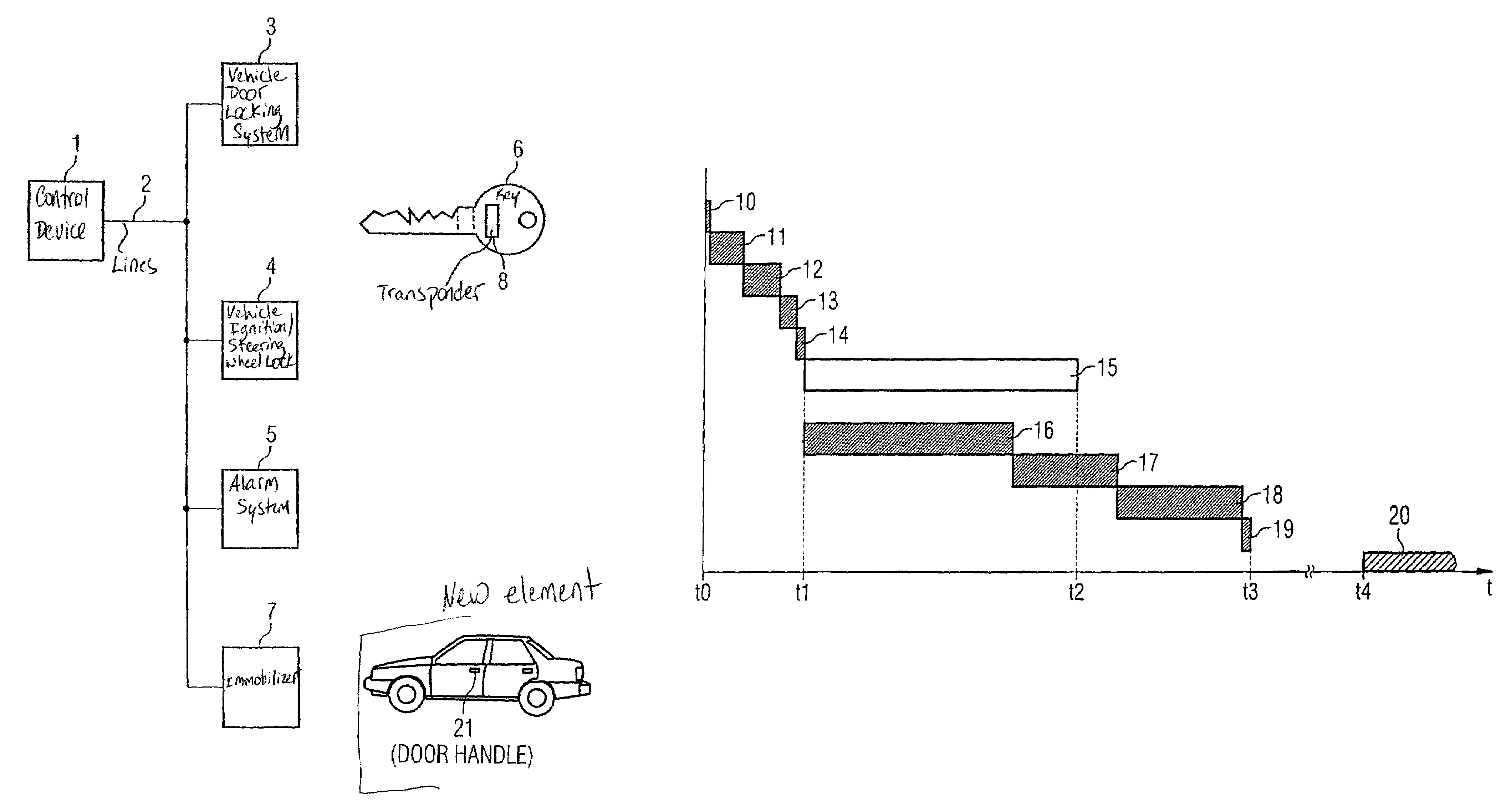
[0039]FIG. 1 shows in a general form a block diagram for an electronic anti-theft system in a motor vehicle, which comprises a control device in the motor vehicle (not shown). The control device 1 uses lines 2, which can be operated bidirectionally, for a connection to communicate with the vehicle door locking system 3, especially a central locking system, the vehicle ignition lock and / or steering wheel lock 4, an alarm system 5, and / or an immobilizer 7. The door locking system 3 and / or the ignition locking system 4 can be activated by an electronic key 6 carried by an operator of the motor vehicle, which can for example be inserted mechanically into one of the locks 3, 4, for activation. In addition, electronic activation of the lock, for example by remote control, is conceivable for opening the doors. The key 6 can be configured in a conventional way, i.e. using the known key-lock principle, or also as a cheque card or chip card.

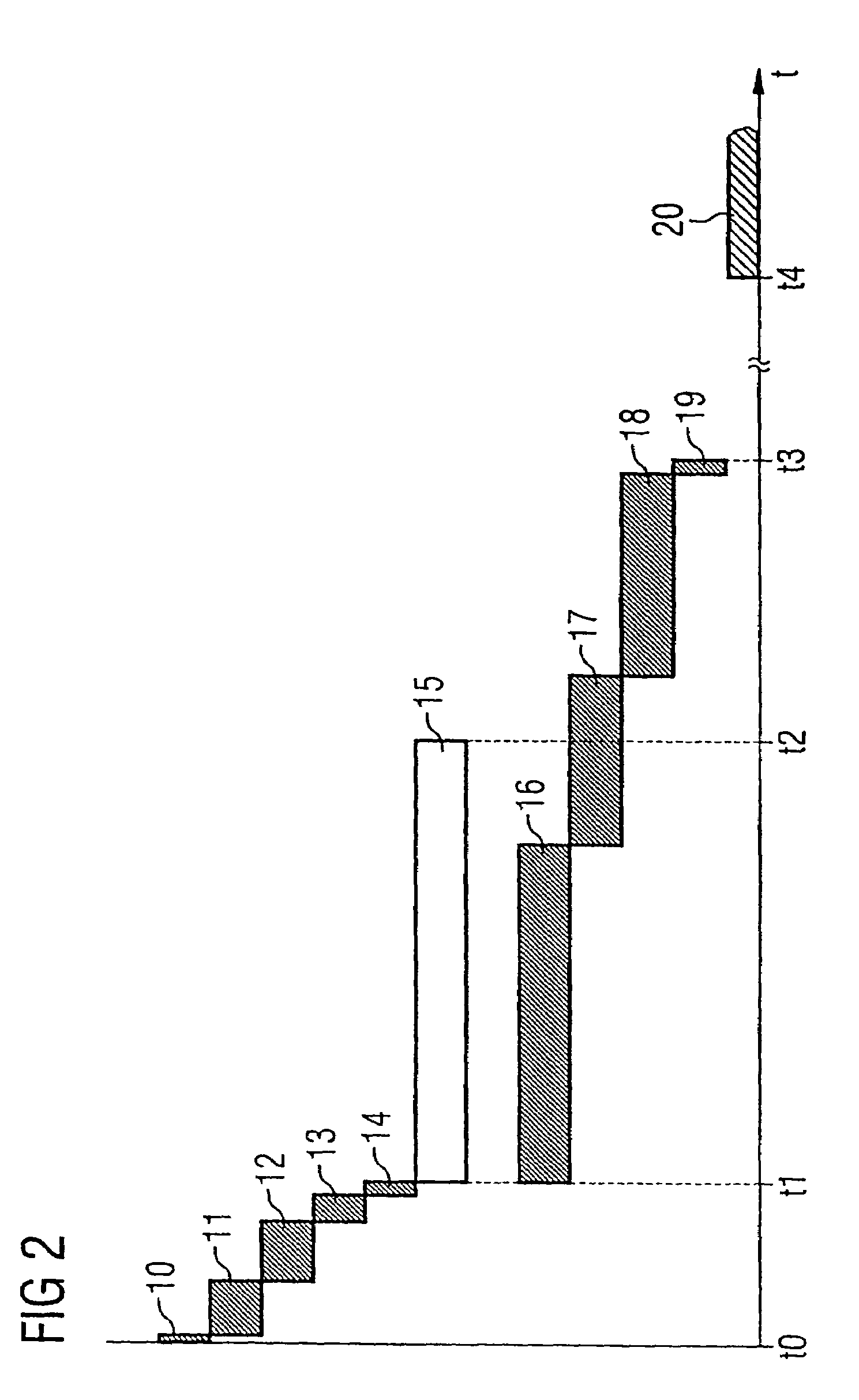
[0040]In addition or alternatively, the access autho...


PUM


Abstract

In a method for operating an electronic anti-theft system, data communication is effected between the control device and the key further to an access authorization request, whereby the control device unlocks the doors and deactivates an alarm system as a function of the data communication. The data communication for unlocking the doors and the data communication for disarming the alarm system are separate from each other. In this way, the mechanical unlocking of the doors can be initiated immediately after the data communication for unlocking the doors. The corresponding data communication for deactivating the alarm system is effected in parallel with this, whereby extensive cryptological data is exchanged between the control device and the key.

Description

PRIORITY[0001]This application claims priority to German Application No. 103 30 807.5 filed Jul. 8, 2003 and German Application No. 103 55 605.2 filed Nov. 28, 2003.TECHNICAL FIELD OF THE INVENTION[0002]The present invention relates to a method for operating an electronic anti-theft system, in particular for motor vehicles, as well as an electronic anti-theft system.BACKGROUND OF THE INVENTION[0003]Modern electronic anti-theft systems comprise an access authorization system, for example, a central locking system, a driver authorization system, for example with an immobilizer and an alarm system. These types of anti-theft systems are disclosed in German Patents DE 199 24 081 A1 and DE 197 56 341 A1.[0004]A modern access authorization system for a motor vehicle comprises an electronic lock in a locking system, which communicates with the electronic key with which it is associated. This lock typically communicates with a control device associated with it, for example the control device...

Claims


Application Information

Patent Timeline
Patent Type & Authority Patents(United States)
IPC IPC(8): G05B19/00H04Q5/22B60R25/04B60R25/24
CPCB60R25/04B60R25/24
Inventor EMMERLING, ULRICHMULLER, AXEL
Owner SIEMENS AG
Why Eureka
Try Eureka