Pressure sensor for a digitizer pen
- Summary
- Abstract
- Description
- Claims
- Application Information
AI Technical Summary
Benefits of technology
Problems solved by technology
Method used
Image

Examples
Embodiment Construction
[0044]It should be understood that the embodiments discussed below are only examples of the many advantageous uses of the innovative teachings herein. In general, statements made in the specification of the present application do not necessarily limit any of the various claimed inventions. Some statements may apply to some inventive features but not to others. In general, unless otherwise indicated, singular elements may be in the plural and vice versa with no loss of generality. The terms first, second, third, and the like, in the description and in the claims, if any, are used for distinguishing between similar elements and not necessarily for describing a sequential or chronological order. The terms top, front, side, and the like, in the description and in the claims, if any, are used for descriptive purposes and not necessarily for describing relative positions. All measurements are approximate.
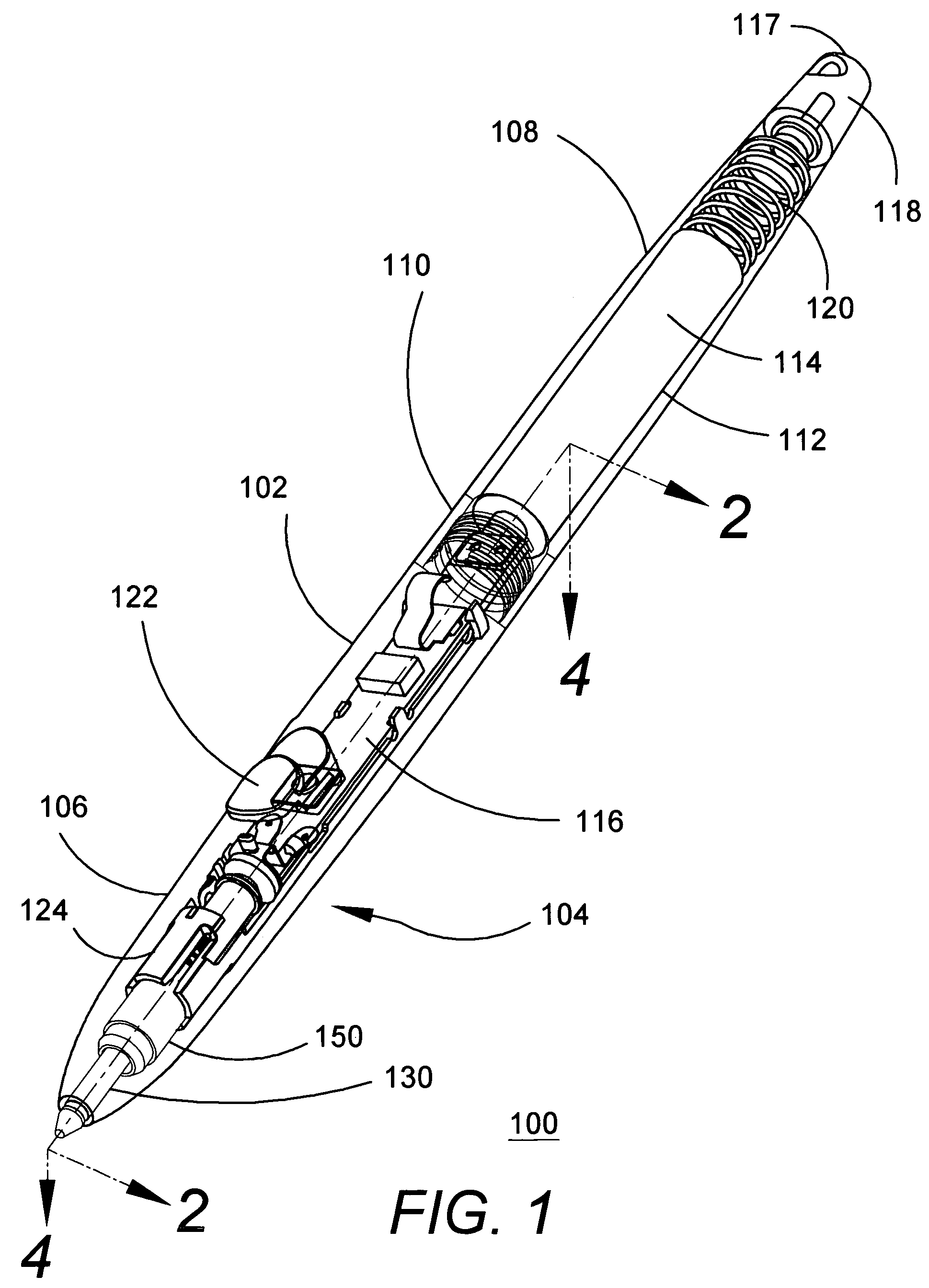
[0045]FIG. 1 is a perspective view of a digitizer pen 100 (hereinafter “pen”) that co...
PUM
 Abstract
Description
Claims
Application Information