Circuit-constituting member and circuit unit

a technology of circuit unit and circuit board, which is applied in the direction of electrical apparatus casing/cabinet/drawer, casing/cabinet/drawer details, coupling device connection, etc., can solve the problems of large radiating member, complex and large radiating member, and heat generated by fets, so as to reduce stress in thus mounted terminals.

Inactive Publication Date: 2007-04-10
AUTONETWORKS TECH LTD +2
View PDF11 Cites 24 Cited by
  • Summary
  • Abstract
  • Description
  • Claims
  • Application Information

AI Technical Summary

Benefits of technology

[0020]In this relay switch, preferably, height of an end portion of the coil-side terminal is higher than that of an end portion of the contact-side terminal by a predetermined thickness. With this construction, the terminals can be mounted

Problems solved by technology

Therefore heat generated from the FETs is liable to remain in the space between the two boards.
Als

Method used


Image

  • Circuit-constituting member and circuit unit
  • Circuit-constituting member and circuit unit
  • Circuit-constituting member and circuit unit

Examples


example 1

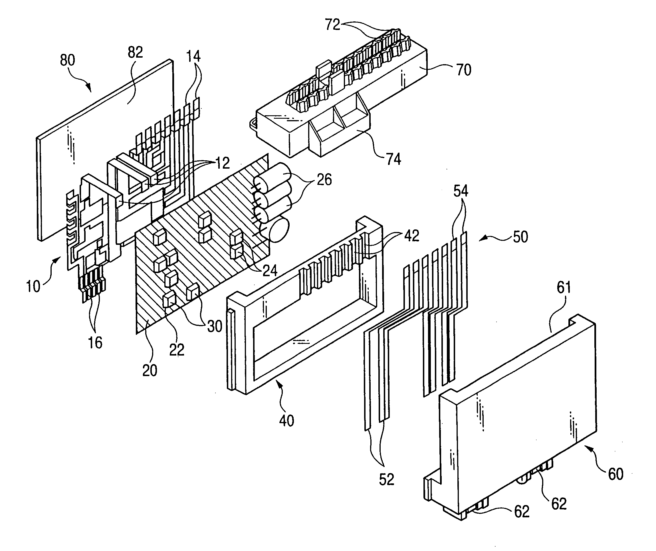
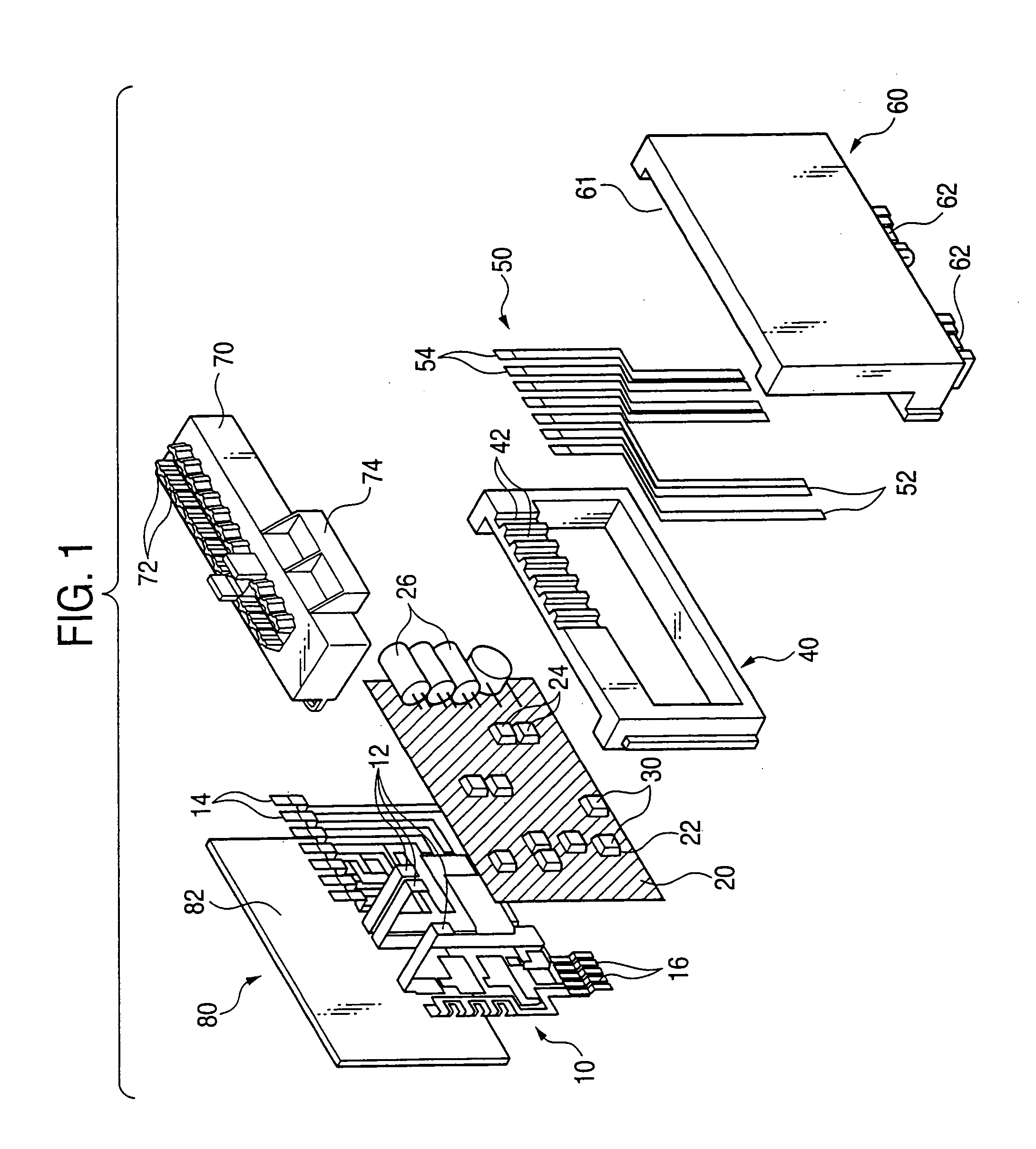
[0040]Conductor patterns are formed on both of opposite sides (front and reverse surfaces) of the control circuit board 20, and an adhesive is coated onto the reverse-side (upper side in FIG. 1) pattern or the bus bar-constituting plate 4, and this reverse-side pattern is adhesively bonded to the upper surfaces of the bus bars. In this case, only the pattern, which will be at the same potential as the bus bars, is provided on the reverses side of the control circuit board 20.

example 2

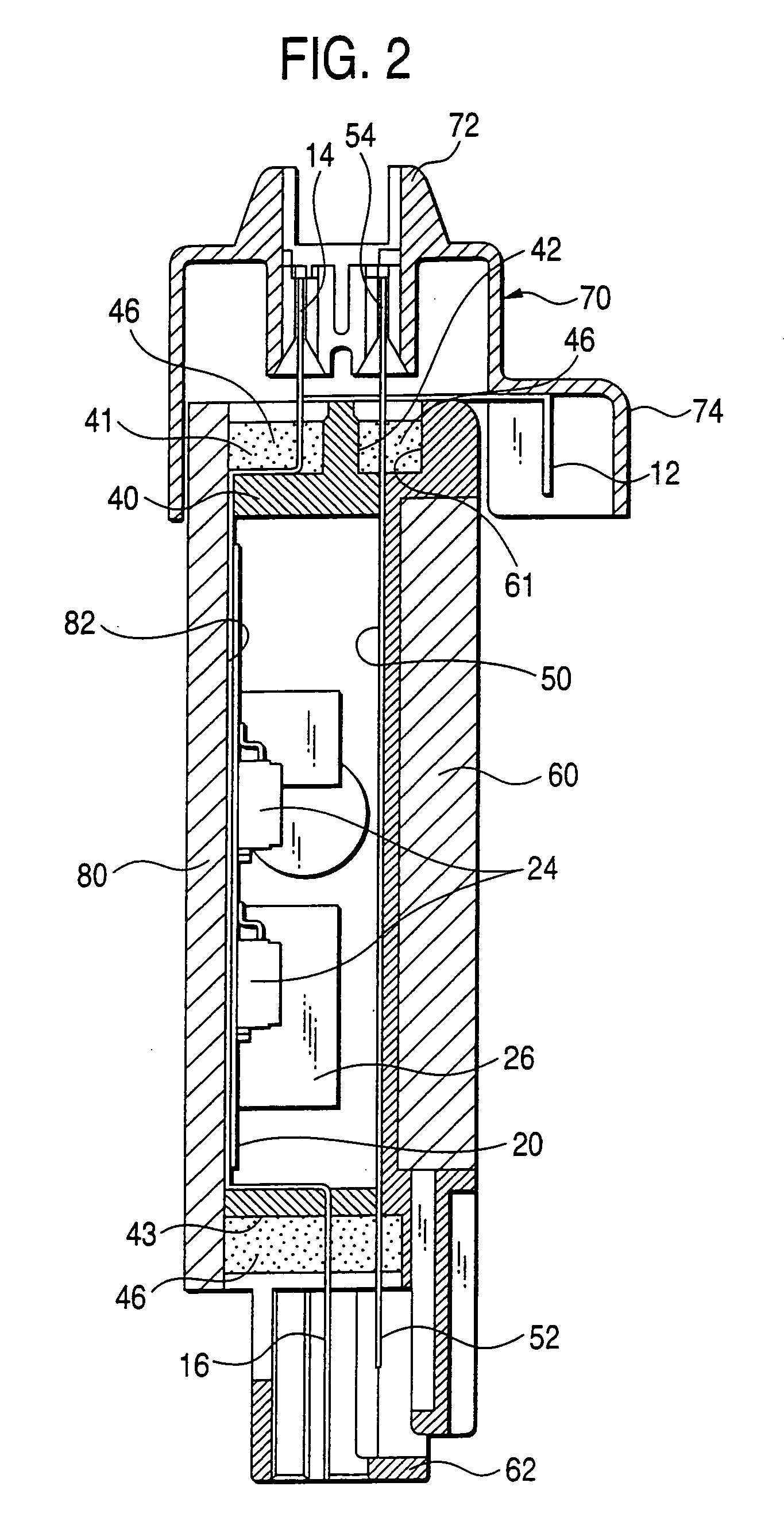
[0041]An insulative adhesive is coated onto the reverse side of the control circuit board 20 or the upper surface of the bus bar-constituting plate. An insulating layer is formed between the control circuit board 20 and the bus bars by this adhesive. In the case where the control circuit board 20 includes through holes, it should be taken care that the insulative adhesive is not adhere to these through hole portions.

example 3

[0042]An adhesive is coated only onto edge portions of the reverse side of the control circuit board 20. This control circuit board is bonded to the upper surfaces of the bus bars. In this case, the bonding areas are only these edge portions, and the control circuit board 20 and the bus bars are free relative to each other at an area inside the bonding areas. Therefore, stresses are reduced.

[0043]3) The relay switches (FET) 30, which are semiconductor switching elements, are connected to both of the control circuit board 20 and the bus bar-constituting plate 4, utilizing the through holes 22 formed in the control circuit board 20. Here, when a distal end portion of the coil-side terminal 36 is stepped upwardly relative to a distal end portion of the contact-side terminal 34 by the thickness of the control circuit board 20, the terminals 34 and 36 can be connected to the bus bar group 10 and the control circuit board 20 regardless of the thickness of the control circuit board 20 with...


PUM


Abstract

A group of bus bars, forming a power circuit, are adhesively bonded to a surface of a control circuit board. Surface-mounting type relay switches are used as a switching unit for the power circuit. Contact-side terminals of each relay switch are mounted on the bus bar group while coil-side terminals thereof are mounted on the control circuit board. The opening and closing of relay contacts are controlled by a control circuit incorporated in the control circuit board.

Description

BACKGROUND OF THE INVENTION[0001]1. Field of the Invention[0002]This invention relates to a circuit-constituting member for forming a power circuit in a vehicle such as an automobile.[0003]2. Description of the Related Art[0004]As a conventional unit for distributing electric power to electronic units from a common on-vehicle power source,there has been known an electric connection box in which a plurality of bus bar boards are stacked together to form a power feed circuit, and fuses and relay switches are incorporated thereinto.[0005]In recent years, in order to achieve a compact design and high-speed switching control of such an electric connection box, there has been developed an electric connection box in which instead of using the relays, semiconductor switching devices such as a FET are provided between input and output terminals.[0006]For example, JP-A-10-35375 discloses an electric connection box which includes a bus bar board forming a current circuit, FETs (semiconductor s...

Claims


Application Information

Patent Timeline
IPC IPC(8): H05K7/06H01R13/71H02G3/16H05K1/02H05K1/14H05K3/20H05K3/34H05K5/00
CPCH05K1/0263H05K1/144H05K3/0061H05K3/202H05K3/3421H05K7/026H05K2201/09063H05K2201/094H05K2201/10053
Inventor KAWAKITA, SHINJIONIZUKA, TAKAHIRO
Owner AUTONETWORKS TECH LTD
Why Eureka
Try Eureka