Analysis of optic nerve head shape

a topographic analysis and optic nerve technology, applied in the field of optic nerve head shape topographic analysis, can solve the problems of requiring time and effort of a skilled technician, affecting the comparison of studies, and allowing the invention to be automated. the effect of facilitating the comparison of studies and complicating the comparison of studies

Inactive Publication Date: 2007-04-10
HEIDELBERG ENG
View PDF7 Cites 13 Cited by
  • Summary
  • Abstract
  • Description
  • Claims
  • Application Information

AI Technical Summary

Benefits of technology

[0008]In one aspect, the present invention provides methods that allow optic nerve head images to be classified objectively by an automated procedure that does not require prior manual outlining of disc boundaries. The present invention may provide particularly advantageous embodiments when the methods of the invention are automated. Automation of the system of the invention is facilitated by the adoption of an approach that includes identifying a centre of analysis of the optic nerve model, rather than defining an area within which the optic nerve is found. In this way, the topographic modelling of the optic nerve head may proceed based on the identification of a centre of analysis, whereas previous approaches have required a human operator to identify an area within which the optic nerve may be found. As such, the automated methods of the invention are not dependent on subjective estimates of the position of the borders of the optic disc, estimates which may vary within and between operators and complicate the comparison of studies done in different centres.

Problems solved by technology

However these defects may only appear after a substantial amount of retinal damage has occurred (Pederson & Andserson, Arch Ophthalmol.
This outlining process has been controversial because different observers do not always agree where the disc margins should be placed and this introduces an element of uncontrolled variability into the morphological analysis (Orgul et al., Graefes Arch Clin Exp Ophthalmol.
Thus, while the art provides a method for interpretation of scanning laser ophthalmoscope 3-dimensional images of ONH surface topography, there is typically a manual component that introduces variability and requires the time and efforts of a skilled technician.

Method used


Image

  • Analysis of optic nerve head shape
  • Analysis of optic nerve head shape
  • Analysis of optic nerve head shape

Examples


example 1

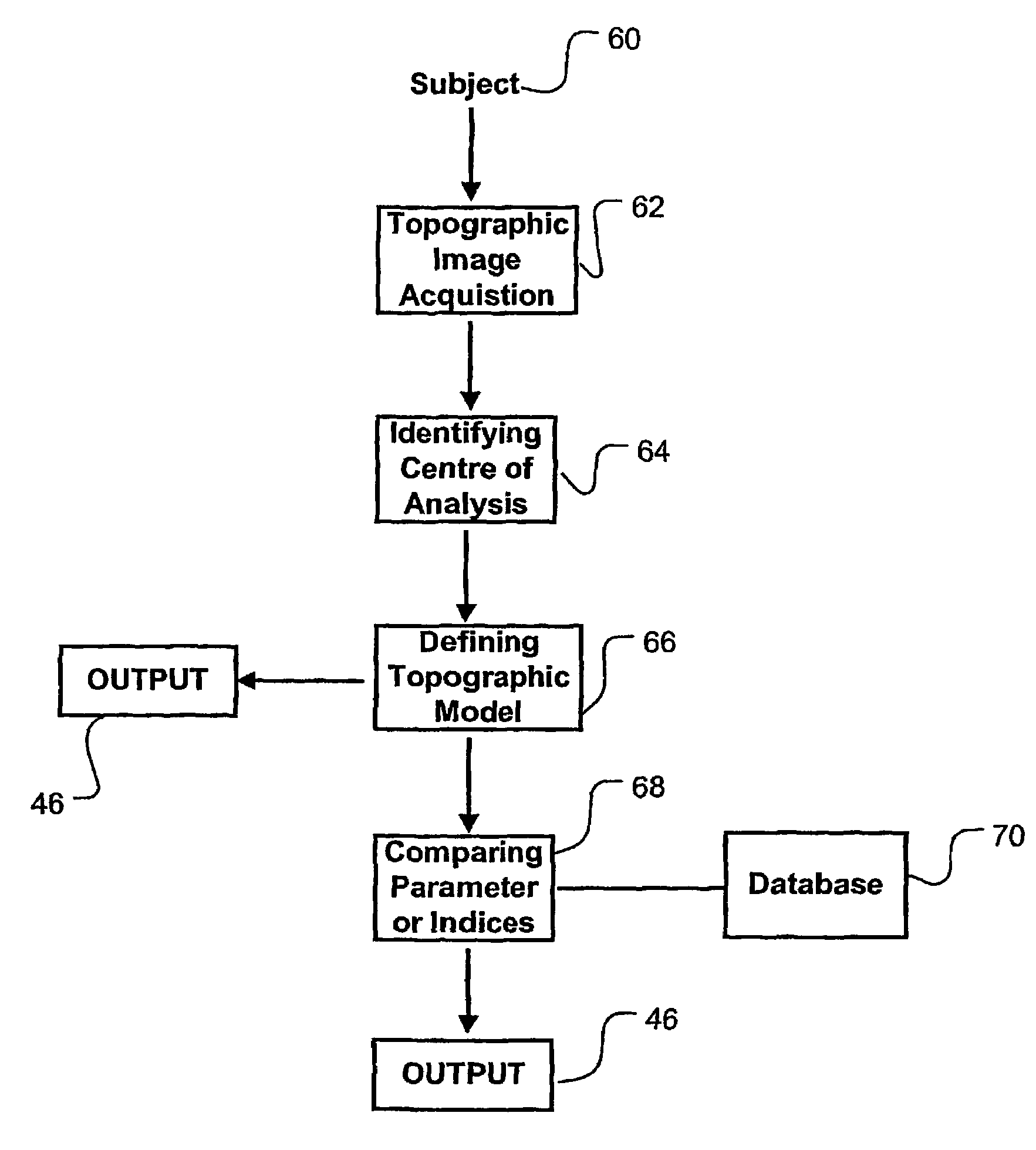
[0057]As an example of the application of the invention, analysis was performed on a database of 100 images obtained from the eyes screened to exclude the presence of glaucoma, and 100 images obtained from eyes with open angles and showing visual field changes indicative of glaucoma. Criteria for subject selection are described in more detail in the following section. The model fitting, analyses and classification are implemented with the aid of a batch processing language which allowed the calculations to be done on each of the images in an automated fashion, without user intervention. To avoid the possibility of artefactual differences between the groups, images from normal and glaucoma patients are intermingled in the analysis sequence. Computations were performed using a 233 MHz Pentium II PC.

Criteria for Subject Selection

[0058]1) Volunteers for the normal group were excluded:[0059](a) if they had eye disease or a history of eye disease known to be related to glaucoma (e.g. pigm...


PUM


Abstract

Methods and apparatus are provided for analysis of 3-dimensional images of an optic nerve head surface topography. Topographic images of the optic nerve head may be analysed to define a topographic model fitted to the topographic image of the optic nerve head about a centre of analysis. The topographic model is defined using model morphological parameters, and the morphological parameters. In some embodiments, the morphological parameters may be used to detect nerve fibre damage or pathology, such as in the diagnosis of glaucoma.

Description

FIELD OF THE INVENTION[0001]The invention relates to methods of topographic analysis of optic nerve head shape, including computational image analysis techniques, which may for example be applied in the diagnosis of glaucoma using a scanning laser ophthalmoscope.BACKGROUND[0002]Glaucoma is a slow and irreversible neuro-degenerative disease whose onset is usually not detected by the patient. Diagnosis may be based on a combination of variables (Quigley, New England Journal of Medicine: 328:1097–1106 (1993); Sommer. Eye: 10:295–30 (1996)) but the most dependable single index is probably the identification of a characteristic pattern of visual field defects. However these defects may only appear after a substantial amount of retinal damage has occurred (Pederson & Andserson, Arch Ophthalmol. 98:490–495 (1980); Quigley et al., Arch Ophthalmol 100:135–146 (1982); Sommer et al., Arch Ophthalmol: 97:1444–1448 (1979), Sommer et al., Arch Ophthalmol: 109:77–83 (1991)). There is a widely acce...

Claims


Application Information

Patent Timeline
Patent Type & Authority Patents(United States)
IPC IPC(8): G06K9/00A61B3/12
CPCA61B3/0025G06T7/0014G06T2207/30041G06T2207/10072
Inventor SWINDALE, NICHOLAS V.CHIN, ADELINEHETHERINGTON, PHILLIP
Owner HEIDELBERG ENG
Why Eureka
Try Eureka