Laser tool

a laser tool and tool head technology, applied in the field of laser tools, can solve the problems of inefficiency, unintended problems, time-consuming and wasteful, and the angle of cutting drywall is too small, and achieve the effect of avoiding the risk of damage to an arm and tight spaces

Inactive Publication Date: 2007-04-17
KATTAR DAVID A
View PDF8 Cites 10 Cited by
  • Summary
  • Abstract
  • Description
  • Claims
  • Application Information

AI Technical Summary

Benefits of technology

[0017]According to another aspect of the present invention, the dial or hub of the present invention operates within the area of the front surface. The present invention eliminates the need for a separate arm for determining angles. Accordingly, the present invention eliminates the risk of damage to an arm. Further, elimination of the arm, coupled with an elongated body having a height substantially less than the length, allows the present invention to be used in relatively tight spaces.
[0018]According to another aspect of the present invention, the laser is projected from an area within the front surface of the present invention. The laser line starts at or near the edge of a surface on which the laser is projected onto. This eliminates segments on the surface of the material that is unmarked by the laser line.

Problems solved by technology

This however, may lead to unintended problems and inefficiencies.
This is both time consuming and wasteful.
In such an event, the person will cut the drywall to too small of angle.
The process of cutting additional sheets of drywall is wasteful.
Using more effort and drywall compound than necessary to finish a wall is both wasteful and time consuming.
However, it is not without some limitations in its own regard.
Also, the angle at the intersection of two surfaces may not be accurate of the true angle between the two surfaces a given distance from the intersection.
When the angle is even slightly incorrect, the error in the cut line will become more significant as the length of the line increases.
Also, a person can forget or become confused as to the proper angle to be cut.
Further, the confusion can become more likely to occur if the person is to remember multiple angles.
A further limitation of conventional protractors is that a person can bump or move one arm with respect to the other.
This could happen before the person reads the angle, causing the person to misread the proper angle.
Further, frequent blows or even a substantial single blow could cause damage to the arms or rotatable pivot.
This product may work well for its intended purposes, but it is not without limitations.
One limitation is that it may be difficult to use the Kell-Strom device in tight spaces, such is in attics to find the angles of the truss.
A further limitation of the Kell-Strom device is, like conventional protractors, that the arm may be damaged if it is hit.
This could lead to both inaccurate readings and premature failure of the device.
A still further limitation of the Kell-Strom device is that the laser projects a beam from an end of the body.
It appears that it is not possible to abut the Kell-Strom device against the side of an object to be cut in order to project a line onto the surface of the object to be cut.
Such a limitation causes less than optimal stability and can lead to inaccurate results.
A still further limitation yet of the Kell-Strom device is that the laser projects from a point remote from the axis of rotation of the arms.
Such a limitation could manifest itself when attempting to determine a cut line relatively close to the axis of rotation, when the laser is more distal than the desired start of the cut line.
A still further limitation yet of the Kell-Strom device is that it is unidirectional.
The device can only be used to determine angles that lie in one direction away from the main body.
Coupled with the size limitations, the person may have difficulty using the Kell-Strom device in certain applications.
Further, the arm in the Kell-Strom device is incapable of a full 360 degrees of rotation relative to the body.

Method used


Image

  • Laser tool
  • Laser tool
  • Laser tool

Examples


Embodiment Construction

[0036]While the invention will be described in connection with a preferred embodiment, it will be understood that it is not intended to limit the invention to that embodiment. On the contrary, it is intended to cover all alternatives, modifications and equivalents as may be included within the spirit and scope of the invention as defined by the appended claims.

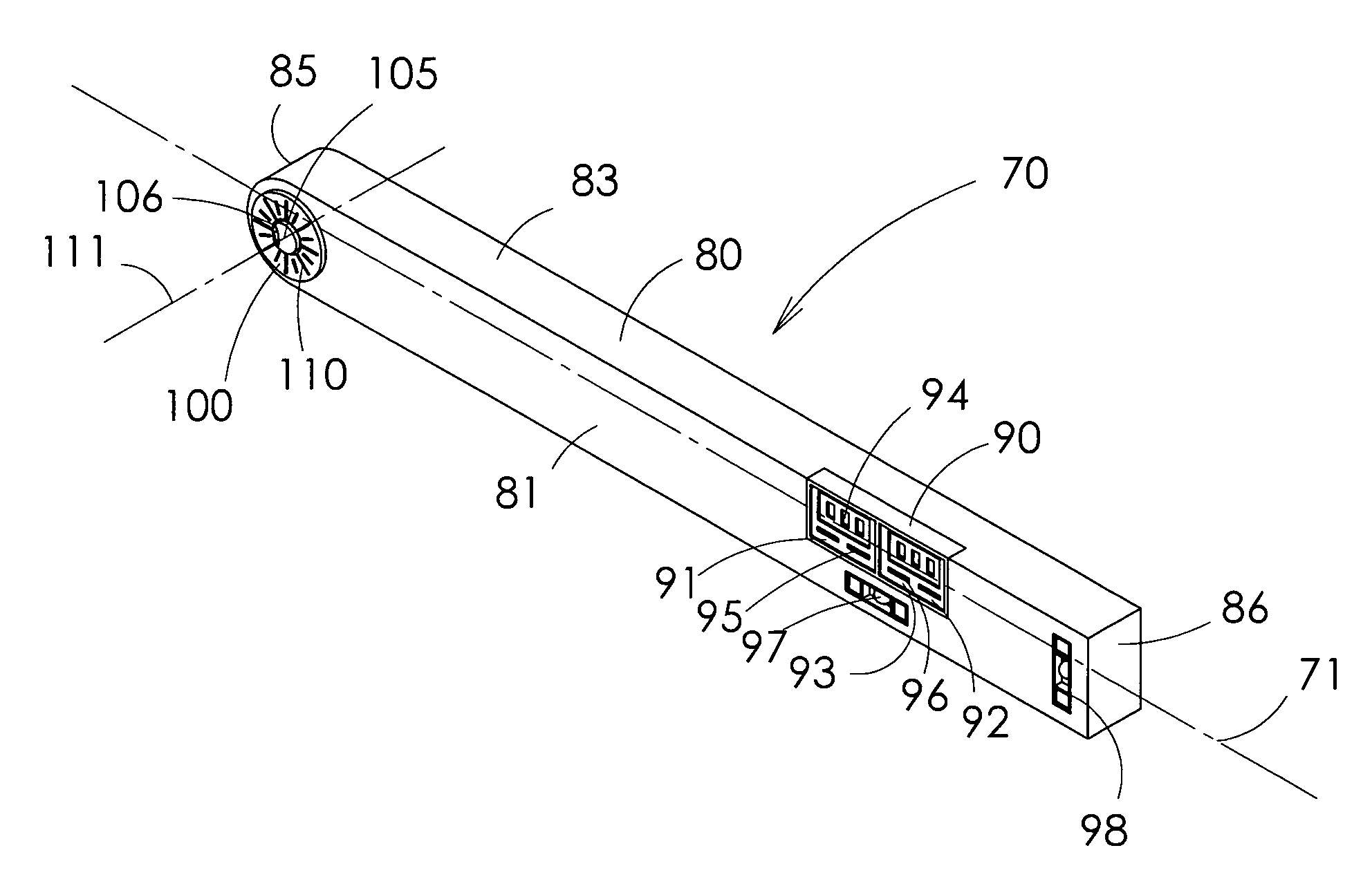
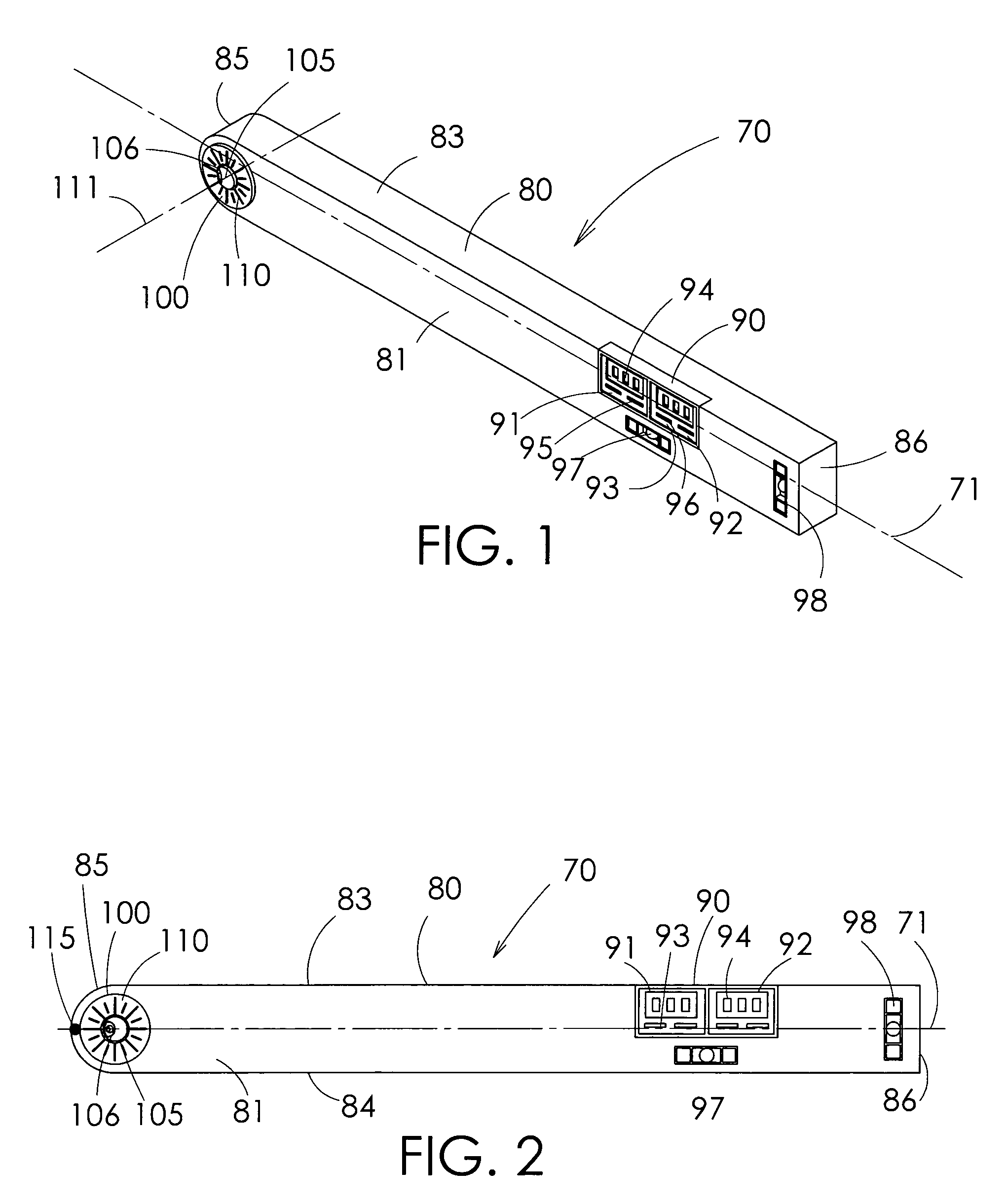
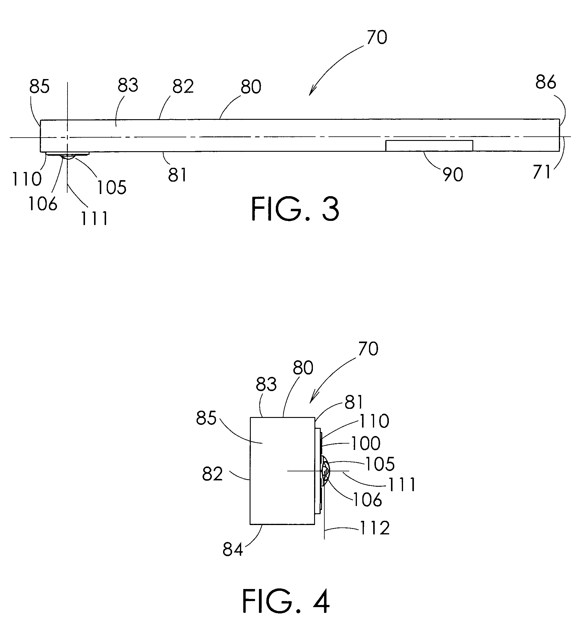
[0037]Turning to FIGS. 1–4, a laser tool 70 is provided. The laser tool 70 has a longitudinal axis 71. The laser tool 70 has a body 80. The body 80 has a front side or surface 81 and an opposed rear side or surface 82. A top side 83 and bottom side 84 are also provided. The body has a first end 85 and a second end 86. The front and rear surfaces 81 and 82 are preferably generally rectangularly shaped, and preferably define respective surface areas that are preferably approximately 2 feet long by 2.5 inches tall. The first end 85 of the front surface is preferably rounded. The front surface 81, rear surface 82, top side 83, bot...


PUM


Abstract

The present invention has a body with front and back surfaces, top and bottom sides, and two opposed ends. A display panel is on the front of the body. A processor is housed within the body. A dial can be connected to the front end of the body. The dial can have a head with an opening therein for allowing a laser beam to be projected from the head. A grid can be on the head for manually determining the angle between the longitudinal axis of the body and the head. The processor can electronically determine the angle between the longitudinal axis of the body and the head. The head can project forward from the front surface of the body. A side of the body can abut the side of a piece of material to be cut. A laser line can then be projected onto the material surface.

Description

BACKGROUND OF THE INVENTION[0001]1. Field of the Invention[0002]The present invention relates to a laser tool, and more particularly to a laser tool that is useful in measuring an angle and for projecting a laser line onto a surface at a predetermined angle from the longitudinal axis of the laser tool.[0003]2. Description of the Related Art[0004]Professional carpenters and homeowners alike frequently need to measure angles and draw chalk lines onto surfaces so that the material can be cut to the measured angle. One situation in particular where people need to measure angles is when cutting drywall, or paneling, to complete the wall of room having a cathedral ceiling. Certainly it will be appreciated that there are many more situations for which the measurement of an angle is necessary. However, for illustrative purposes, this situation in particular will be described.[0005]Several methods have been used in order to determine and cut drywall at a desired angle. Perhaps the simplest w...

Claims


Application Information

Patent Timeline
Patent Type & Authority Patents(United States)
IPC IPC(8): G01B3/56
CPCG01B3/56G01C1/00G01C15/002
Inventor KATTAR, DAVID A.
Owner KATTAR DAVID A
Why Eureka
Try Eureka