Wire harness including hook and loop shaped attaching members and a method of attaching a wire harness using the same

a technology of wire harnesses and attaching members, which is applied in the direction of insulated conductors, cable connections, coupling devices, etc., can solve the problems of time and effort involved in attaching operation, and achieve the effect of reducing the space provided by the cord

Active Publication Date: 2007-04-17
YAZAKI CORP
View PDF9 Cites 17 Cited by
  • Summary
  • Abstract
  • Description
  • Claims
  • Application Information

AI Technical Summary

Benefits of technology

[0013]It is an object of the present invention to provide a wire harness that can be used even when front and back surfaces of the wire harness are reversed and a wire harness attaching method.
[0014]Also, it is another object of the present invention to provide a wire harness and a wire harness attaching method capable of reducing a cord providing space.

Problems solved by technology

However, in the flat harness laminated structure in JP-UM-A-6-64324, the problems described in the following exist.
Therefore, the worker must turn the flat harness in his or her hand upside down and then push it once again, so that such attaching operation takes a lot of time and effort.

Method used


Image

  • Wire harness including hook and loop shaped attaching members and a method of attaching a wire harness using the same
  • Wire harness including hook and loop shaped attaching members and a method of attaching a wire harness using the same
  • Wire harness including hook and loop shaped attaching members and a method of attaching a wire harness using the same

Examples


first embodiment

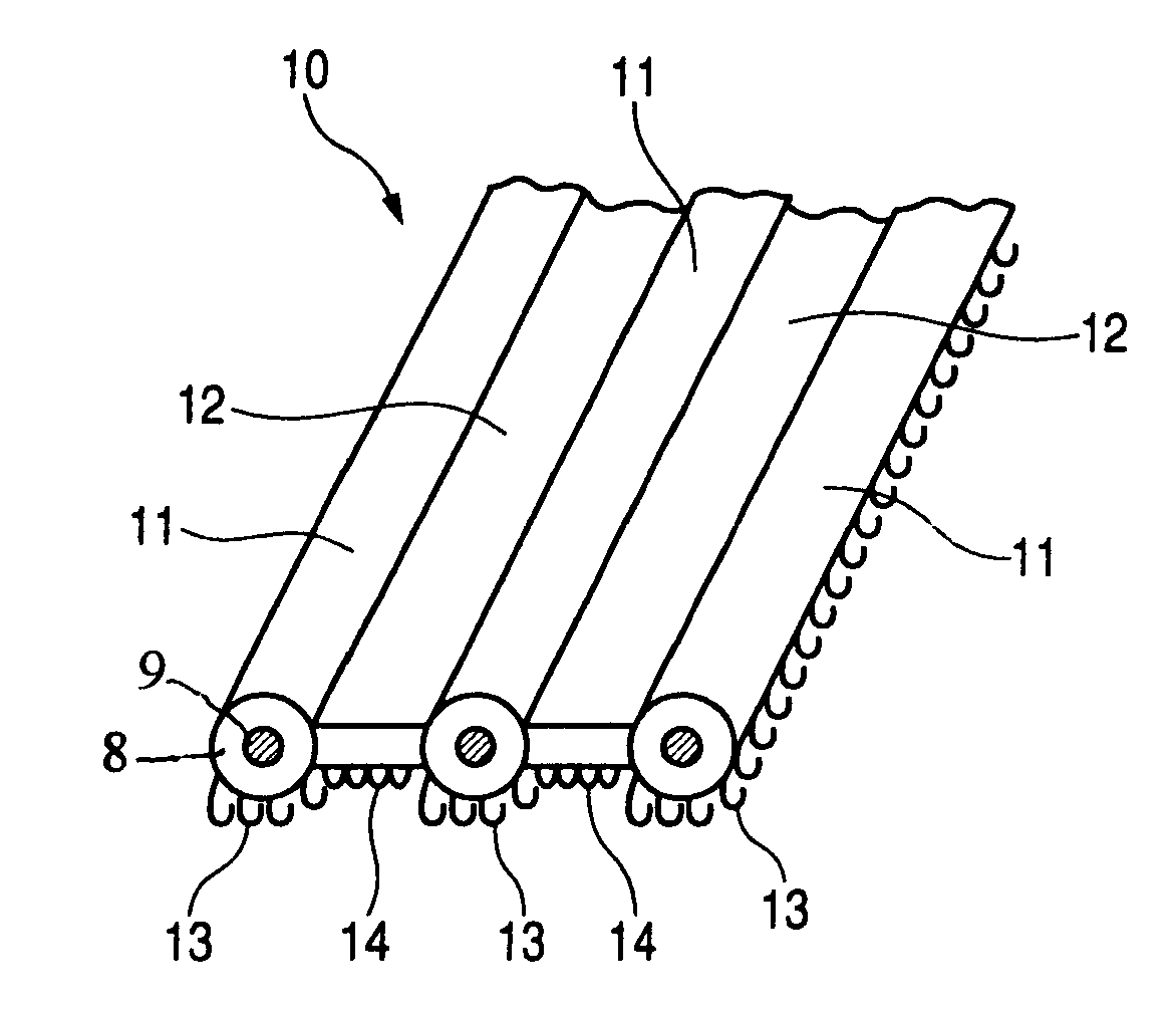
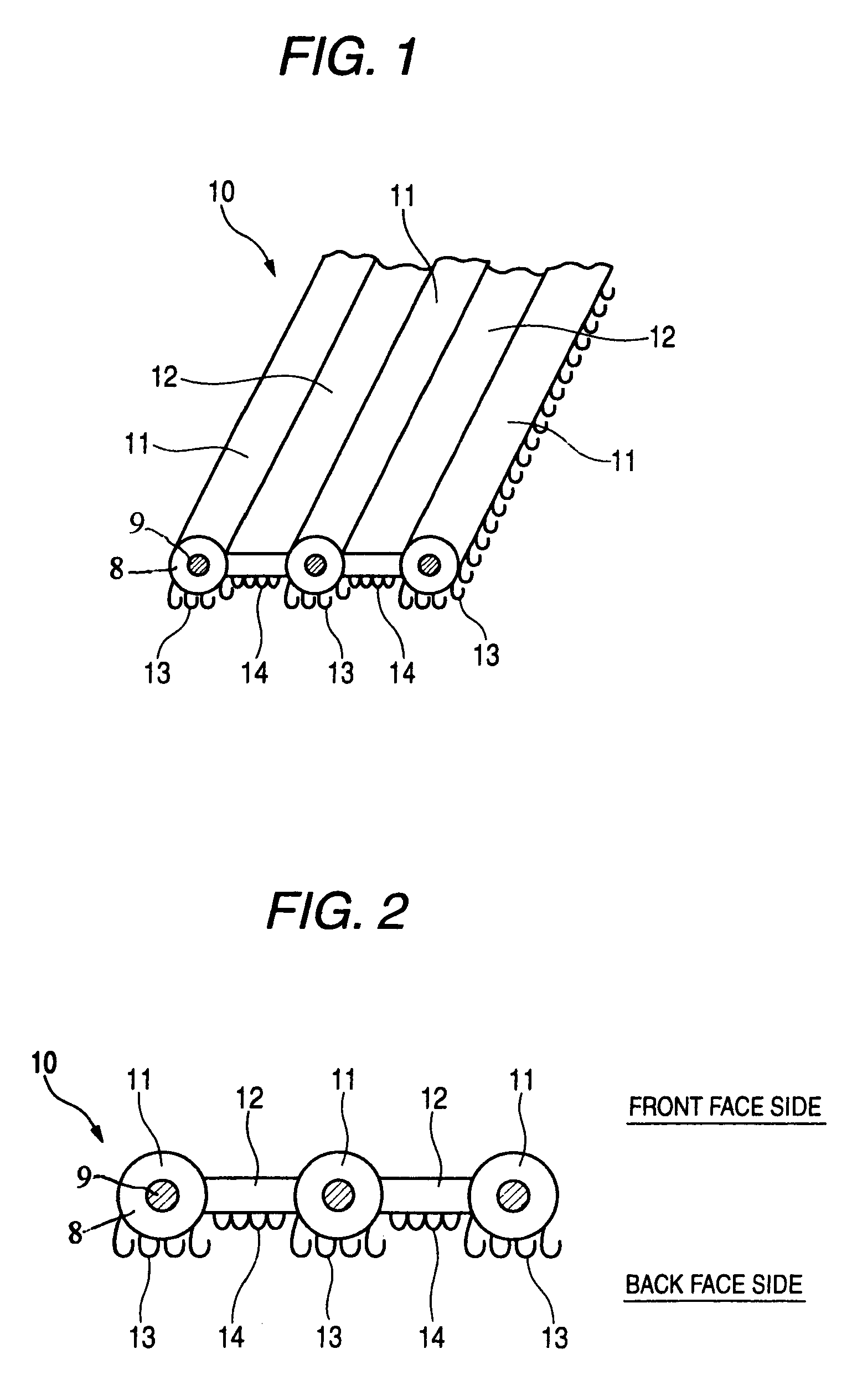
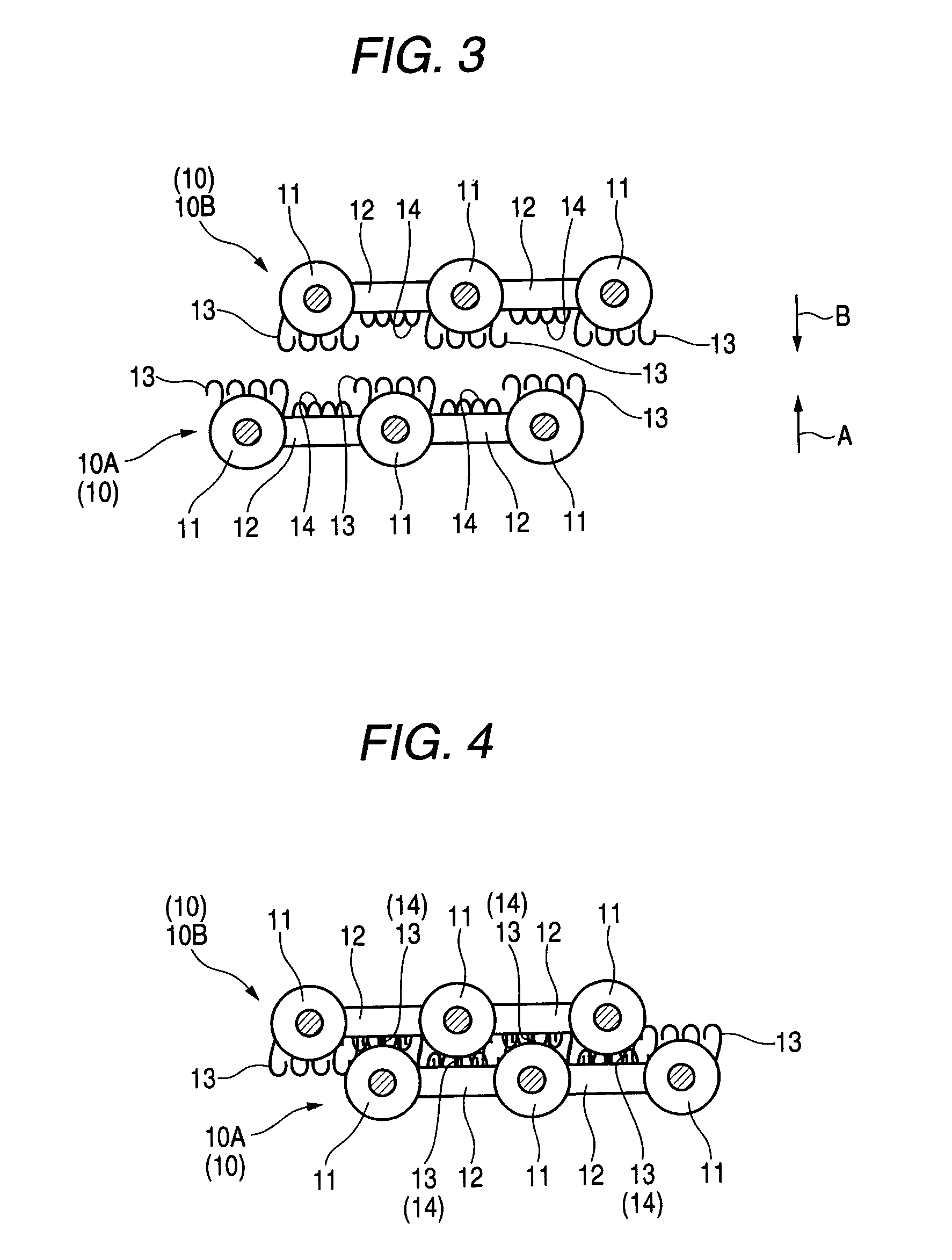
[0049]A flat type wire harness 10 is shown in FIG. 1 and FIG. 2 respectively, and a wire harness attaching method of attaching a plurality of the wire harnesses 10 is shown in FIG. 3 and FIG. 4 respectively.

[0050]The wire harness 10 includes an insulating portion 8 that contain conductors 9 therein. More specifically, the wire harness includes cylindrical conducting portions 11 arranged in three rows, for example, and serving as an insulator portion made of a synthetic resin, or the like, and bridge portions 12 for coupling these conducting portions 11. The wire harness 10 is manufactured to have a predetermined length. Although not shown, a core electric wire as a predetermined conducting portion is contained in the inside of the conducting portion 11 to continue in one direction. The bridge portion 12 is formed like a thin plate whose thickness is smaller than a diameter of the conducting portion 11. This bridge portion 12 is provided on a line that connects both centers of neigh...

second embodiment

[0058]Next, the present invention will be explained with reference to FIG. 5 and FIG. 6 hereunder.

[0059]A wire harness 20 of the present embodiment is that the loop-shaped members 14 are implanted on the front face and also the hook-shaped members 13 are implanted on the back face.

[0060]As shown in FIG. 5, the wire harness 20 is formed to have the conducting portions 11 and the bridge portions 12. Also, the hook-shaped members 13 are implanted on the back face of the conducting portions 11, and the loop-shaped members 14 are implanted on the front face of the bridge portions 12.

[0061]In attaching two sheets of wire harnesses 20 constructed as above, as shown in FIG. 6, first the front face of a first wire harnesses 20A and the back face of a second wire harnesses 20B are arranged to oppose to each other. That is, the first wire harnesses 20A is arranged to direct the loop-shaped members 14 upward and the second wire harnesses 20B is arranged to direct the hook-shaped members 13 down...

third embodiment

[0064]Next, the present invention will be explained with reference to FIG. 7 and FIG. 8 hereunder.

[0065]A wire harness 30 of the present embodiment is that the hook-shaped members 13 and the loop-shaped members 14 are implanted on both front and back faces.

[0066]As shown in FIG. 7, the wire harness 30 is formed to have the conducting portions 11 and the bridge portions 12. Also, the hook-shaped members 13 are implanted on both front and back faces of the conducting portions 11, and the loop-shaped members 14 are implanted on both front and back faces of the bridge portions 12.

[0067]In attaching three sheets of wire harnesses 30 constructed as above, as shown in FIG. 8 first a first wire harnesses 30A and a second wire harnesses 30B are arranged to oppose to each other.

[0068]At this time, the wire harness 30A and the wire harness 30B are arranged to shift in their width direction such that the conducting portions 11 of the wire harness 30A are overlapped with the bridge portions 12 o...


PUM

PropertyMeasurementUnit
thicknessaaaaaaaaaa
energyaaaaaaaaaa
insulatingaaaaaaaaaa

Abstract

A wire harness includes an insulating member that contains a conductor therein, the conductor extending along one direction, and the insulating member having a front face and a back face that is opposed to the front face and a plurality of hook-shaped members and a plurality of loop-shaped members that are provided on at least one of the first face and the back face of the insulating member. The hook-shaped members are engageable to loop shaped members of a mating wire harness to be laminated to the wire harness. The loop-shaped members are engageable to hook shaped members of the mating wire harness.

Description

BACKGROUND OF THE INVENTION[0001]The present invention relates to a wire harness fitted to a car, or the like and a wire harness attaching method and, more particularly, a wire harness that can be installed even when front and back faces of the wire harness are reversed and can reduce a cord providing space and a wire harness attaching method.[0002]The progress in a car, a copying machine, a ticket machine, etc. equipped with electronic equipments has been notable in recent years. The wire harness is employed as the wiring system to transfer information and energy that are indispensable for these equipments.[0003]For example, several hundreds of high-performance electric wires are needed to operate precisely an engine, meters, lights, etc. of the car. The wire harness is employed to tie up such electric wires and information circuits compactly in a bundle.[0004]As the wire harness, normally there are the flat type in which core electric wires as conductors are aligned like a flat su...

Claims


Application Information

Patent Timeline
Patent Type & Authority Patents(United States)
IPC IPC(8): H01R29/00
CPCH01B7/40H01B7/08Y10T29/49208
Inventor YAMAMOTO, MASATAKA
Owner YAZAKI CORP
Why Eureka
Try Eureka