Phacoemulsification needle

a technology of ultrasonic surgical instruments and phacoemulsification needles, which is applied in the field of phacoemulsification needles for ultrasonic surgical instruments, can solve the problems of disruption of continuation of surgery and time-consuming handpiece replacement, and achieve the effect of saving tim

Inactive Publication Date: 2007-04-17
ART LTD
View PDF24 Cites 439 Cited by
  • Summary
  • Abstract
  • Description
  • Claims
  • Application Information

AI Technical Summary

Benefits of technology

[0025]With this ball-shaped or curved tip design and the opening arranged at the distal end or the at least two openings being arranged in the region of said distal end, it is possible to remove both the cataract nucleus and the residual cortex.
[0026]This tip can be used for irrigati

Problems solved by technology

It takes time to change the handpiece and t

Method used


Image

  • Phacoemulsification needle
  • Phacoemulsification needle
  • Phacoemulsification needle

Examples


third embodiment

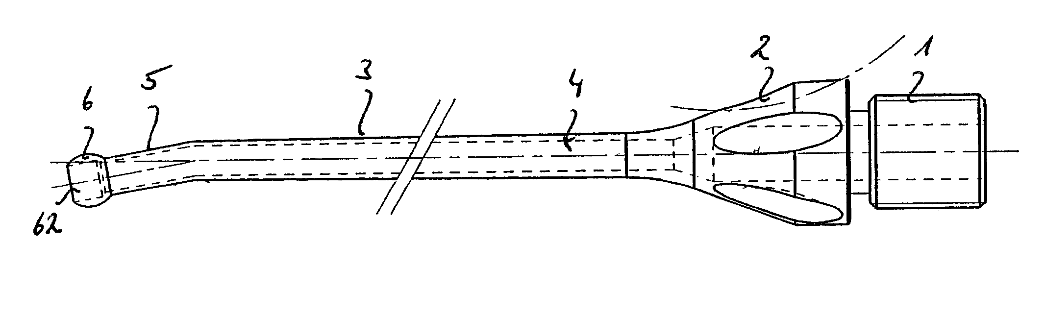
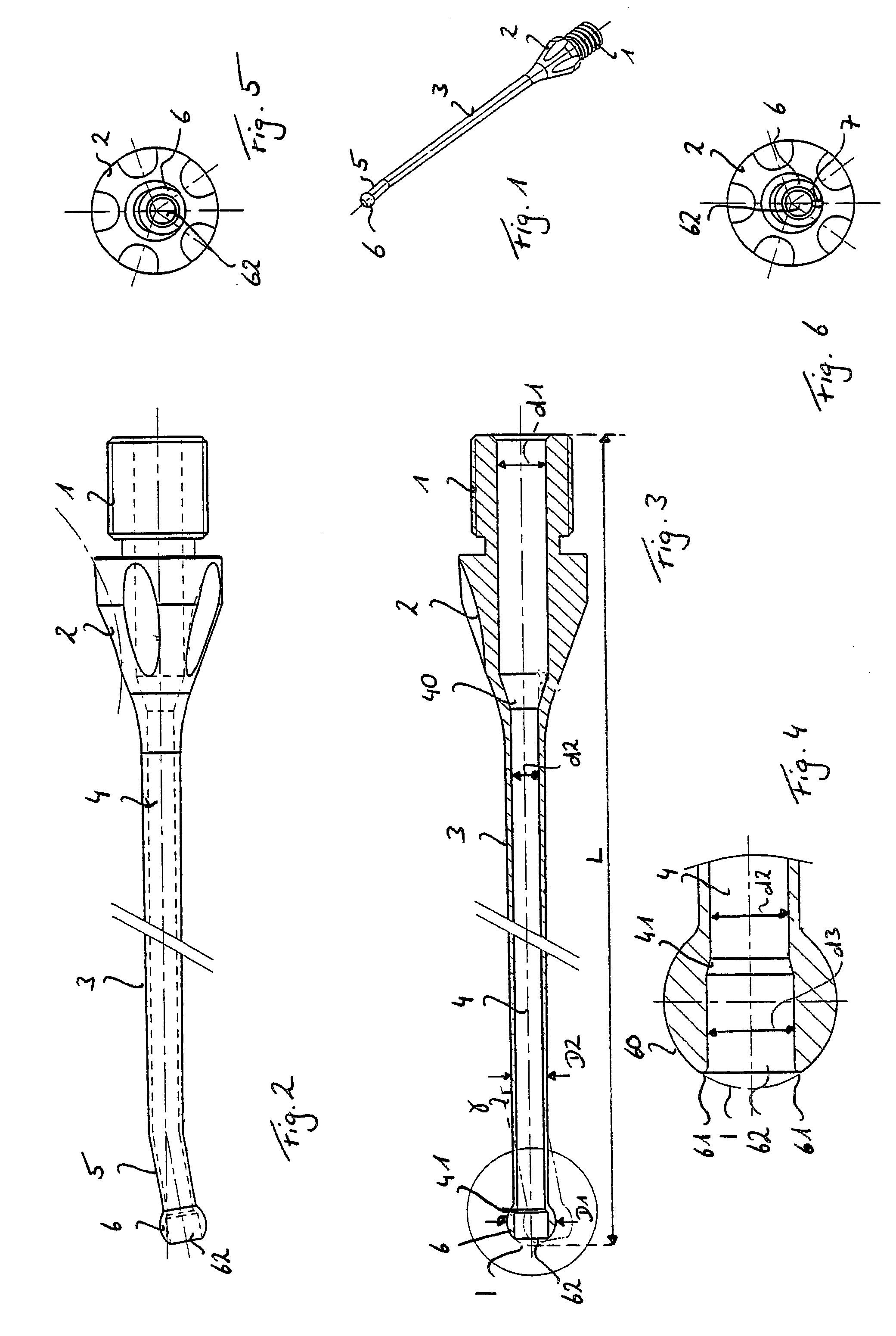
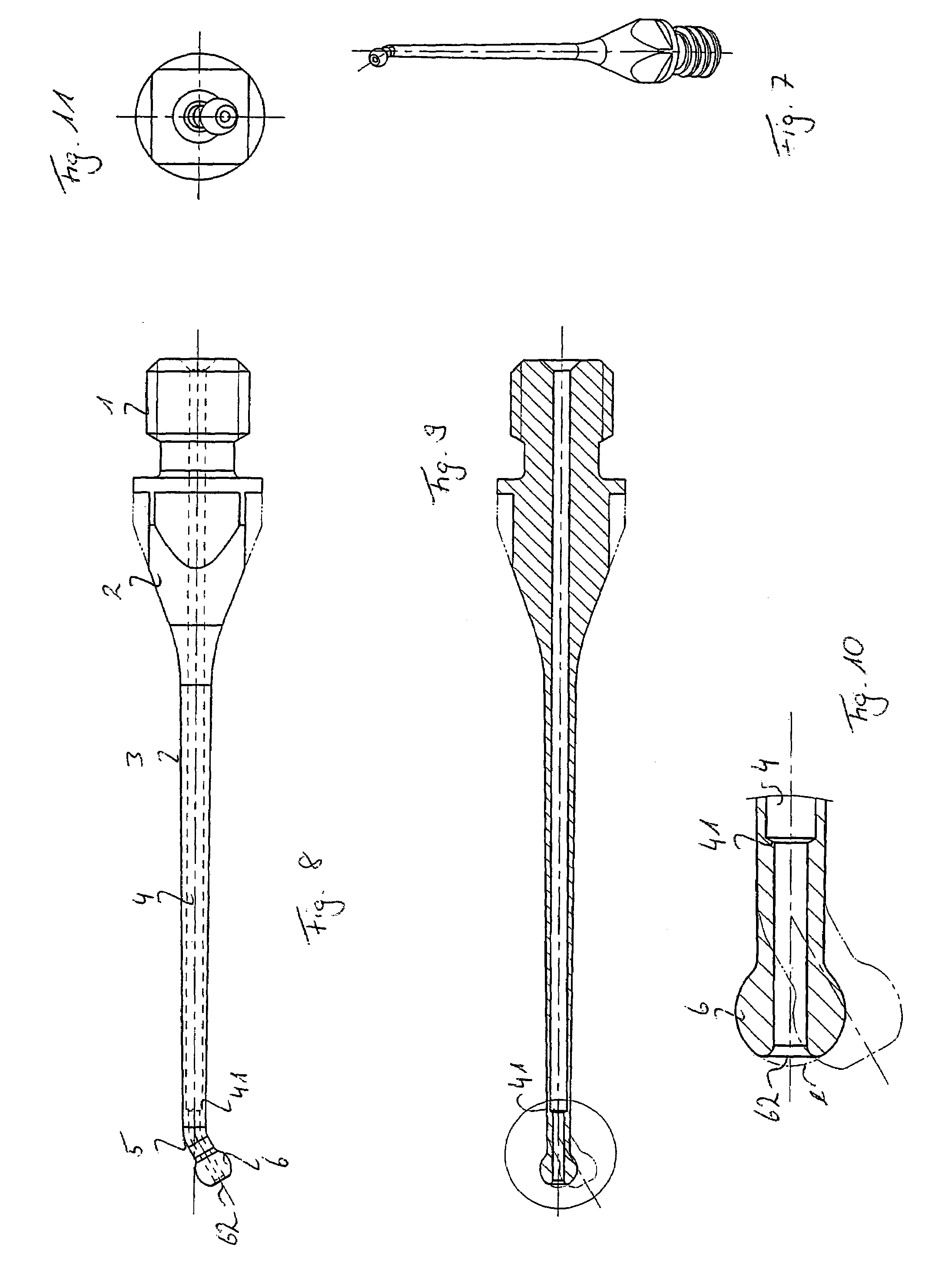
[0064]FIGS. 7 to 11 show the needle according to the invention. The threaded portion 1 is slightly shorter than the one shown in FIG. 2. The hub 2 has not a generally circular cross section but a rectangular, preferably a quadratic one. This hub 2 and this threaded portion 1 can also be used with the tips disclosed in the other embodiments and the hup and threaded portion disclosed in FIG. 2 can be used with this tip.

[0065]The aspiration lumen 4 extending through the needle shaft 3 comprises a second step 41 like the one shown in FIG. 1. However, this second step 41 is arranged is located outside of the tip 6. This second step 41 is in this case preferably arranged behind the angled portion 5. If the shaft 3 is rectilinear, the second step 41 is preferably arranged in a distance behind the tip 6 which has approximately the same length as the tip 6. This step 41 reduces the cross section of the lumen 4. In addition, no first step is located within the hub 2.

[0066]This second step 41 ...

fifth embodiment

[0069]FIGS. 16 to 18 show the invention. Here, there exists no second step 41, neither in the shaft 3 nor in the tip 6. This embodiment can be used with the opening 8 or the slit 7 or without any of them. Furthermore, any of the above mentioned embodiments can comprise the opening 8 as well as the slit 7.

sixth embodiment

[0070]A sixth embodiment is shown in the FIGS. 19 to 21. The first and second steps 40 and 41 can be arranged or being nonexistent as described in any of the previous embodiments. Furthermore, this embodiment can comprises an opening 8 and / or a slit 7 or none of them. The tip 6 of this embodiment still has a curved shaped. This embodiment however comprises instead of the flat distal end 62 being defined by a distal opening of the lumen 4 at least two openings 63 of the lumen 4 being arranged in the region of the distal end 62. Here, we have such four openings 63. However, there can also be three, five or more openings. Preferably, the are arranged in a symmetrical manner around the longitudinal axis A defined by the shaft 3. These openings 63 have like the single opening of the other embodiments blunt or rounded edges 61. In order to communicate with these openings 63, the lumen 4 is divided into sublumens 4′, each sublumen 4′ ending in one of the mentioned openings 63. This divisio...


PUM


Abstract

The phacoemulsification needle according to the invention comprises a shaft, a tip disposed at a distal end of said shaft, the tip having a larger outer diameter than said shaft and an aspiration lumen extending through said shaft and said tip. The tip has an opening communicating with said aspiration lumen, a ball-shaped surface and a flat distal end comprising said opening. This needle can be used for removal of the cataract nucleus as well as for removal of the residual tissue.

Description

FIELD OF THE INVENTION[0001]This invention relates to a phacoemulsification needle for an ultrasonic surgical instrument, the needle being designed for promoting cavitation in eye tissue and for the removal of fragmented lens from the eye.BACKGROUND OF THE INVENTION[0002]Phacoemulsification has become the preferred form of cataract, i.e. a cloudy eye lens, removal. One of the main advantages of phacoemulsification is, that only a small incision into the cornea or sclera of an eye is needed to remove the cataract. Furthermore, the removal of the cataract can be done very quickly. After the cataract is removed, an intraocular lens is inserted to replace the original lens.[0003]The phacoemulsification technique uses a hand held microsurgical tool known as phacoemulsifier. This phacoemulsifier comprises a handpiece and a small diameter needle with a tip to be inserted into the small incision of the eye. The needle and therefore the tip are vibrated by an ultrasonic source. It breaks the...

Claims


Application Information

Patent Timeline
IPC IPC(8): A61F9/00A61B17/20A61B17/32A61M25/00A61M5/00A61F9/007A61M1/00
CPCA61F9/00745A61B2017/320072A61B2017/32008A61B2017/320073
Inventor AKAHOSHI, TAKAYUKI
Owner ART LTD
Why Eureka
Try Eureka