High precision current sensor
a current sensor, high-precision technology, applied in the direction of instruments, measurement devices, measurement using dc-ac conversion, etc., can solve the problems that the error correction method of rom cannot be applied to the current sensor for measuring the current of the battery, and it is difficult to correct the measurement error, so as to achieve accurate measurement of a large current
- Summary
- Abstract
- Description
- Claims
- Application Information
AI Technical Summary
Benefits of technology
Problems solved by technology
Method used
Image
Examples
first embodiment
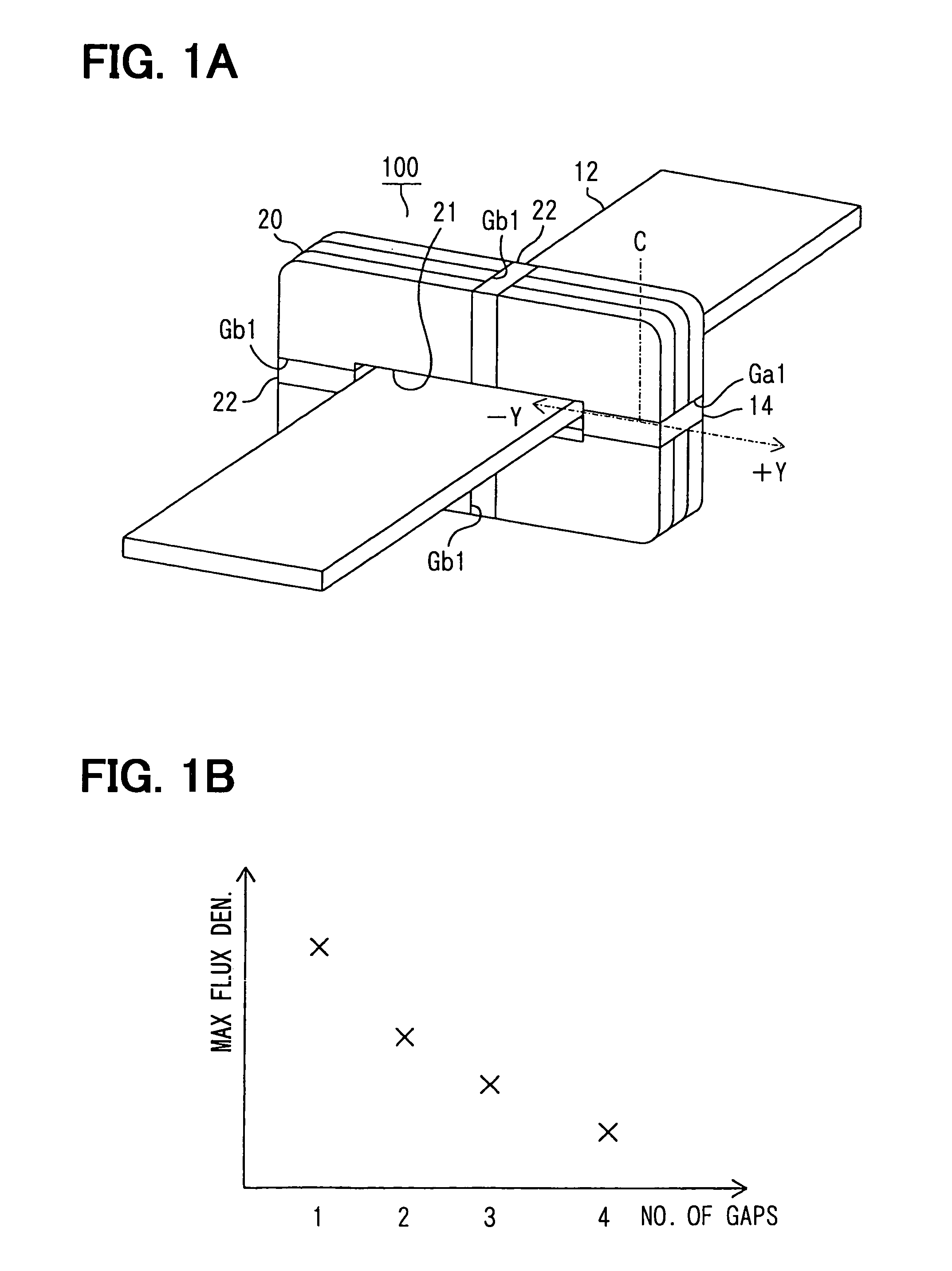
[0034]The inventors have preliminary studies about a current sensor for improving magnetic saturation. There is a potential method for overcoming magnetic saturation. Expanding the width of the gap Ga1 of the sensor 10 increases leakage flux in the core 20, and thereby magnetic saturation can be prevented. However, this method requires that the magnetic sensor 14 is exactly disposed in a center of the gap Ga1. The reason is as follows:
[0035]Graphs illustrated in FIG. 16 show a relation between magnetic flux density and a position in the gap Ga1, when a given amount of current flows. A vertical axis represents magnetic flux density, and a horizontal axis represents a deviation from the center C of the gap Ga1 to ±Y direction. A solid line graph represents the sensor 10 with one gap Ga1. A chain double-dashed line graph represents a wider gap version of the sensor 10. The flat area in the middle of each graph indicates effective sensing area for the magnetic sensor 14. When the magnet...
second embodiment
[0055]A current sensor 200 according to a second embodiment of the present invention is shown in FIG. 8A. The sensor 200 is designed to measure a battery current. As shown in FIG. 8A, the sensor 200 includes a magnetic core 20, a current bus bar 12, a first magnetic sensor 14A and a second magnetic sensor 14B. The core 20 has a center opening 21 and two gaps Ga1, Ga2. The core 20 is evenly divided into an upper half 24A and a lower half 24B by the gaps Ga1, Ga2. The magnetic sensor 14A, 14B are disposed in the gaps Ga1, Ga2, respectively. The bar 12 is disposed in a plane perpendicular to the core 20 and inserted in the opening 21 with a given space until the core 20 is positioned in the middle of the bar 12. The magnetic sensors 14A, 14B detect magnetic flux density in the gaps Ga1, Ga2, respectively, generated by a current flowing through the bar 12.
[0056]The same Hall effect devices are employed in each magnetic sensor 14A, 14B as its magnetic sensing element. Consequently, the t...
third embodiment
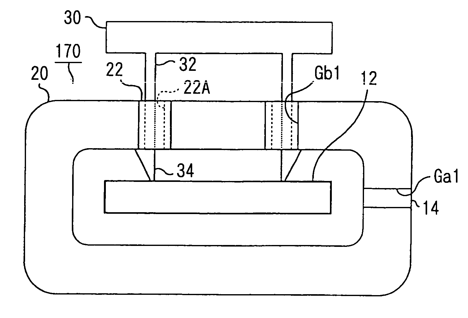
[0083]A current sensor 300 according to a third embodiment of the present invention is shown in FIG. 17. The sensor 300 includes two gaps G, Gb1. One of the gaps G is composed of different width gaps Ga3, Ga4, which is similar to the sensor 230 shown in FIG. 13. The other one of gaps Gb1 is disposed opposite to the gap G, which is similar to the sensor 100 shown in FIG. 1A. Here, the sensor 300 can include multiple gaps Gb1 shown in FIG. 1A. For example, the sensor 300 can include three gaps Gb1.
[0084]Thus, the sensor 300 according to the third embodiment is formed to combine the sensor 100 according to the first embodiment and the sensor 230 according to the second embodiment. Here, in the sensor 100 according to the first embodiment, the magnetic core 20 is divided into multiple parts so that the magnetic saturation is reduced. Therefore, to flow a large current in the core 20, it is required to increase the number of the parts. However, when the sensor 100 includes the large numb...
PUM
 Abstract
Description
Claims
Application Information
 - R&D
- Intellectual Property
- Life Sciences
- Materials
- Tech Scout
- Unparalleled Data Quality
- Higher Quality Content
- 60% Fewer Hallucinations
Browse by: Latest US Patents, China's latest patents, Technical Efficacy Thesaurus, Application Domain, Technology Topic, Popular Technical Reports.
© 2025 PatSnap. All rights reserved.Legal|Privacy policy|Modern Slavery Act Transparency Statement|Sitemap|About US| Contact US: help@patsnap.com


