Method and system for beam expansion in a display device

a display device and beam technology, applied in the field of display devices, can solve the problems of degrading the quality of the reproduced virtual image, the display no longer qualifies as an ned, etc., and achieve the effect of increasing the amount of diffracted ligh

Active Publication Date: 2007-04-17
MAGIC LEAP INC
View PDF13 Cites 261 Cited by
  • Summary
  • Abstract
  • Description
  • Claims
  • Application Information

AI Technical Summary

Benefits of technology

[0016]It is an objective to the present invention to provide an exit pupil extender wherein the relative amount of different color components in the exit beam is more consistent with that of the input beam. In order to compensate for the uneven amount in the diffracted color components in the exit beam, the exit pupil extender, according to the present invention, comprises a plurality of layers having additional diffraction gratings so as to increase the amount of diffracted light for those color components with a lower amount.
[0033]According to the present invention, the optical device further comprises a filter disposed between the first diffractive element in the first layer and the first diffractive element in the second layer so as to reduce the amount of the first wavelength component in the second part of the exit beam.
[0034]According to the present invention, the optical device further comprises another filter disposed between the first diffractive element of the second layer and the first diffractive element of the third layer so as to reduce the amount of the second wavelength component in the second part of the exit beam and the amount of the second wavelength component in the third part of the exit beam.
[0038]The second aspect of the present invention provides a method of improving color uniformity in an exit beam in an optical device, the optical device having
[0053]disposing a filter between the first diffractive element in the first layer and the first diffractive element in the second layer so as to reduce the amount of the first wavelength component in the second part of the exit beam and the amount of the first wavelength component in the third part of the exit beam;
[0054]disposing another filter between the first diffractive element of the second layer and the first diffractive element of the third layer so as to reduce the amount of the second wavelength component in the second part of the exit beam and the amount of the second wavelength component in the third part of the exit beam.

Problems solved by technology

Thus, such a display no longer qualifies as an NED, for obvious reasons.
The EPE, such as that shown in FIG. 1, results in color non-uniformity, thereby degrading the quality of the reproduced virtual image.

Method used


Image

  • Method and system for beam expansion in a display device
  • Method and system for beam expansion in a display device
  • Method and system for beam expansion in a display device

Examples


Embodiment Construction

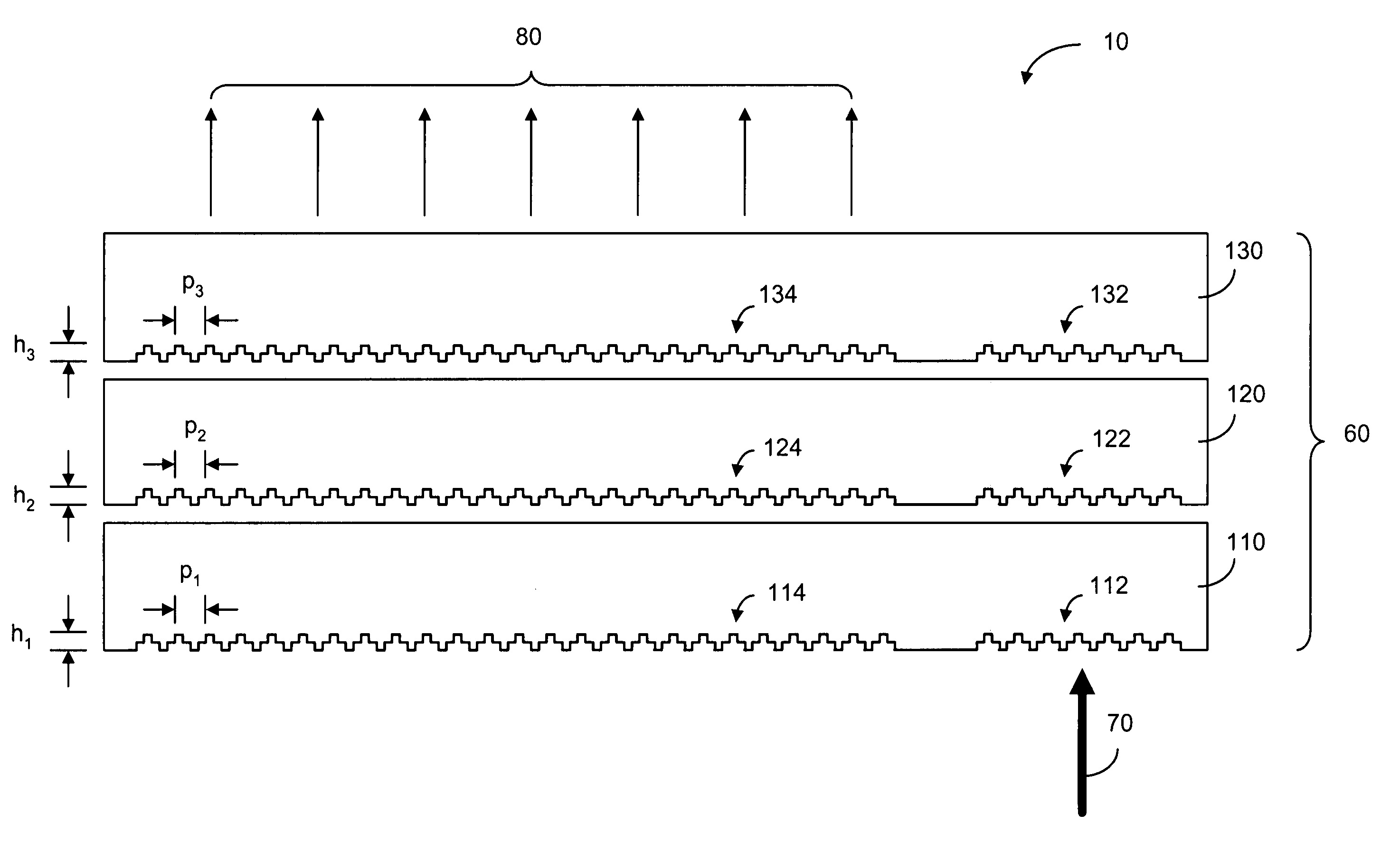
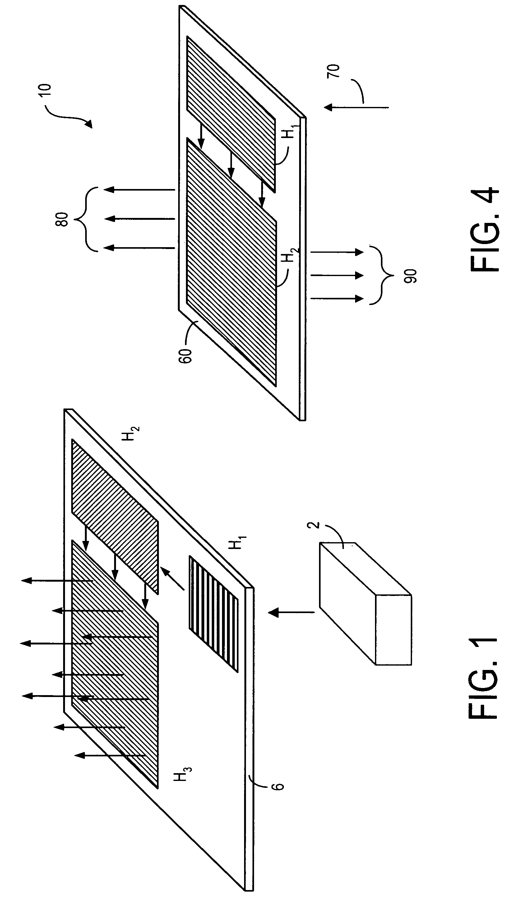
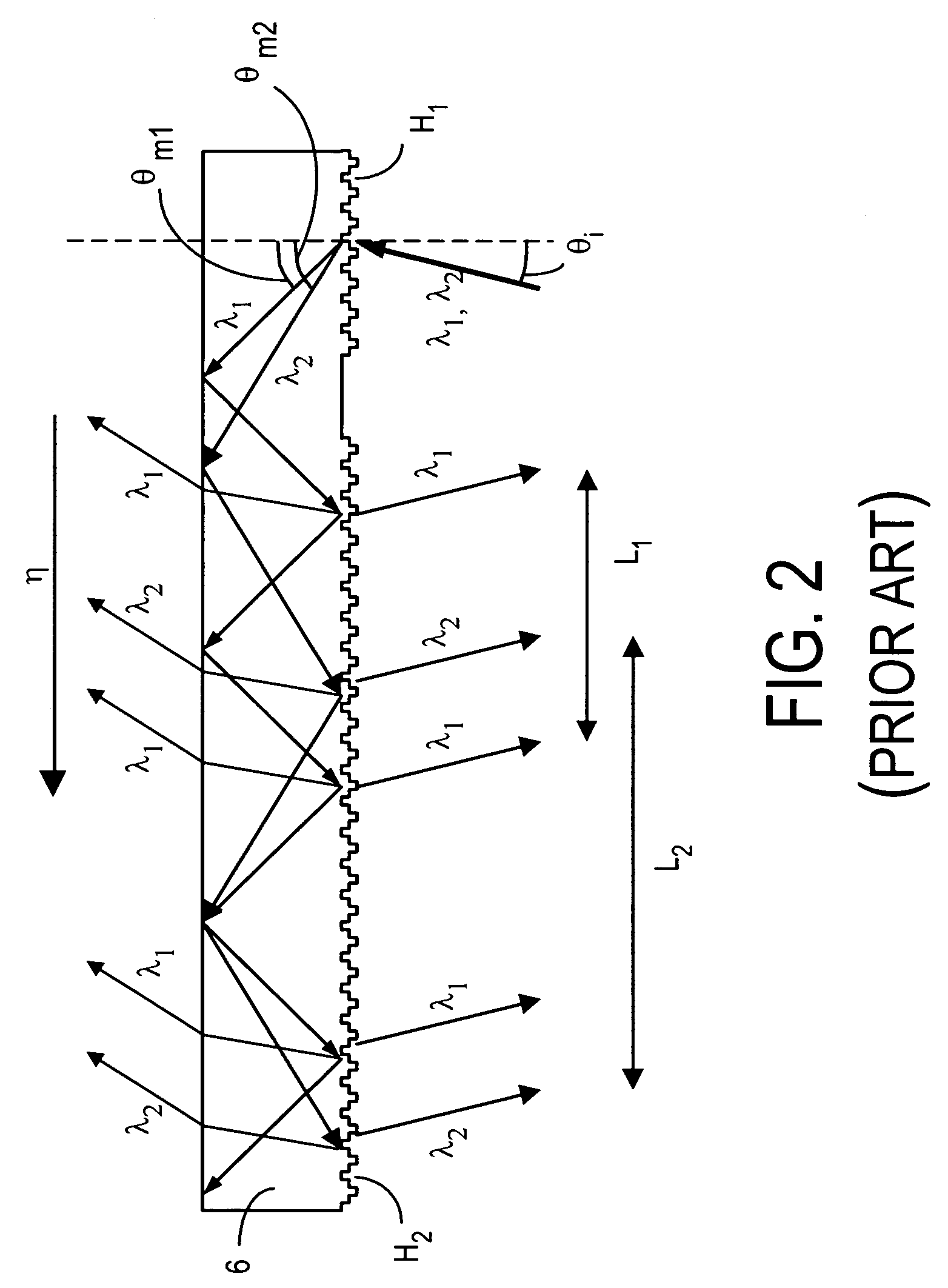
[0098]Instead of using a homogeneous substrate 6, as shown in FIG. 2, the exit pupil extender (EPE) 10, of the present invention, uses a substrate 60 comprising a plurality of layers, each layer having a diffraction grating, as shown in FIGS. 3a–3d.

[0099]As shown in FIG. 3a, the substrate 60 has three layers of optical material 110, 120 and 130. The first layer 110 has an input diffraction grating 112 and an output diffraction grating 114. Likewise, the second layer 120 has an input diffraction grating 122 and an output diffraction grating 124, and the third layer 130 has an input diffraction grating 132 and an output diffraction grating 134. As shown in FIG. 3a, an incoming light beam 70 having red, green and blue components (RGB) enters the substrate 60 through the input grating 112 on the first layer 110. After being diffracted in gratings 112, 122 and 132, the light beam is broadened and exits through the upper surface of the third layer 130. The exit light beam is denoted by r...


PUM


Abstract

An exit pupil extender wherein the relative amount of different color components in the exit beam is more consistent with that of the input beam. In order to compensate for the uneven amount in the diffracted color components in the exit beam, the exit pupil extender, comprises a plurality of layers having additional diffraction gratings so as to increase the amount of diffracted light for those color components with a lower amount. Additionally, color filters disposed between layers to reduce the diffracted light components with a higher amount.

Description

FIELD OF THE INVENTION[0001]The present invention relates generally to a display device and, more specifically, to a display that uses one or more diffractive elements for extending the exit pupil of the display for viewing.BACKGROUND OF THE INVENTION[0002]While it is a common practice to use a low-resolution liquid-crystal display (LCD) panel to display network information and text messages in a mobile device, it is preferred to use a high-resolution display to browse rich information content of text and images. A microdisplay-based system can provide full color pixels at 50–100 lines per mm. Such high-resolution is generally suitable for a virtual display. A virtual display typically consists of a microdisplay to provide an image and an optical arrangement for manipulating light emerging from the image in such a way that it is perceived as large as a direct view display panel. A virtual display can be monocular or binocular.[0003]The size of the beam of light emerging from imaging...

Claims


Application Information

Patent Timeline
Patent Type & Authority Patents(United States)
IPC IPC(8): G03H1/00
CPCG02B27/4277G02B27/4205G02B27/0081G02B6/0016G02B6/0038G02B27/4272
Inventor LEVOLA, TAPANI
Owner MAGIC LEAP INC
Why Eureka
Try Eureka