Optic array for three-dimensional multi-perspective low observable signature control

Inactive Publication Date: 2007-04-17
ALDEN RAY M
View PDF8 Cites 6 Cited by
  • Summary
  • Abstract
  • Description
  • Claims
  • Application Information

AI Technical Summary

Benefits of technology

[0013]Accordingly, several objects and advantages of the present invention are apparent. It is an object of the present invention to create a three dimensional virtual image bubble surrounding or on the surface of objects and people. Observers looking at this three dimensional bubble from any viewing perspective are only able to see the background of the object through the bubble. This enables military vehicles and operatives to be more difficult to detect and may save lives in many instances. Likewise, police operatives operating within a bubble can be made difficult to detect by criminal suspects. The apparatus is designed to be rugged, reliable, and light weight.
[0014]The electronic embodiment can alternatively be used as a r

Problems solved by technology

This enables military vehicles and operatives to be more difficult to detect and may save lives in many instan

Method used


Image

  • Optic array for three-dimensional multi-perspective low observable signature control
  • Optic array for three-dimensional multi-perspective low observable signature control
  • Optic array for three-dimensional multi-perspective low observable signature control

Examples


Embodiment Construction

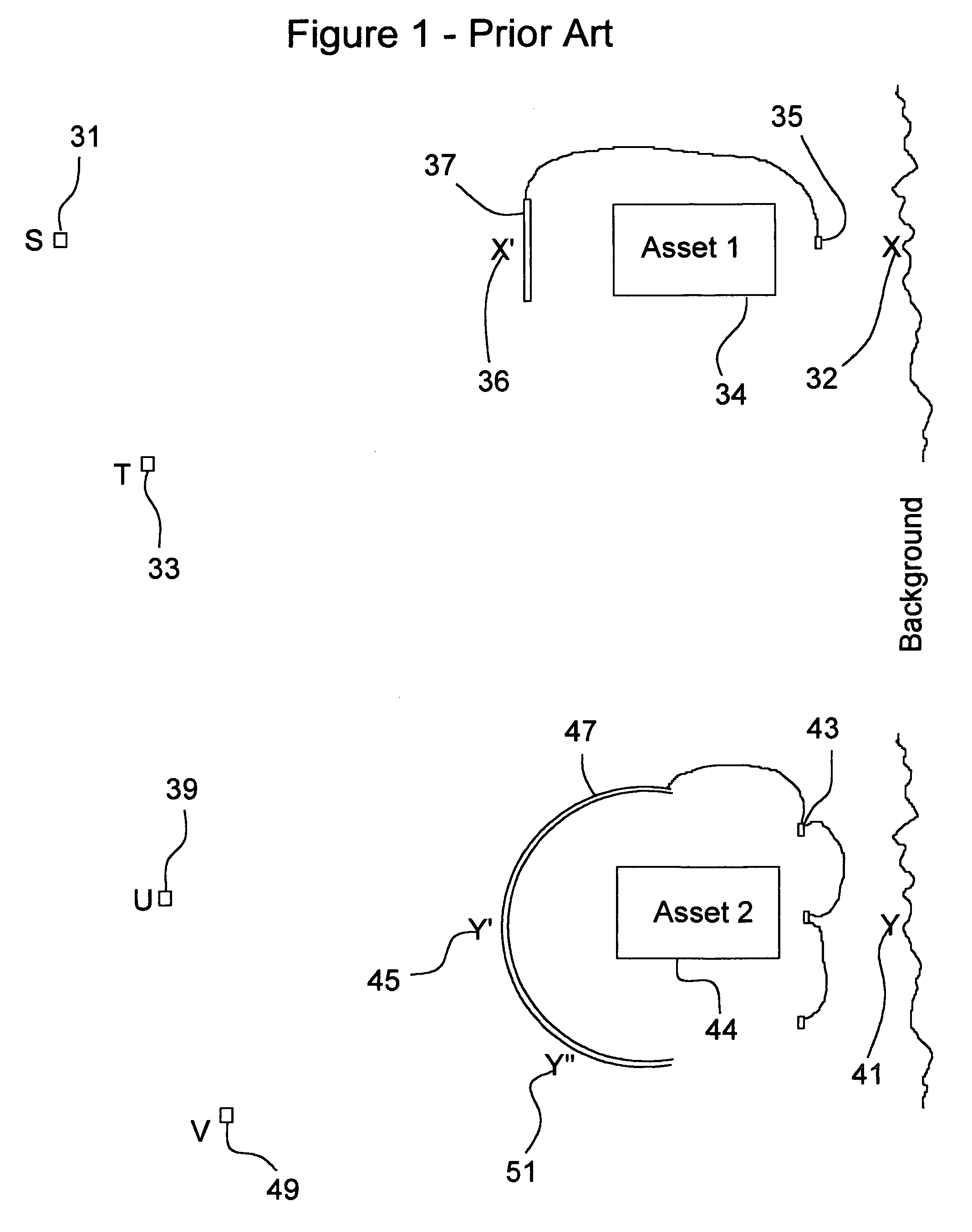
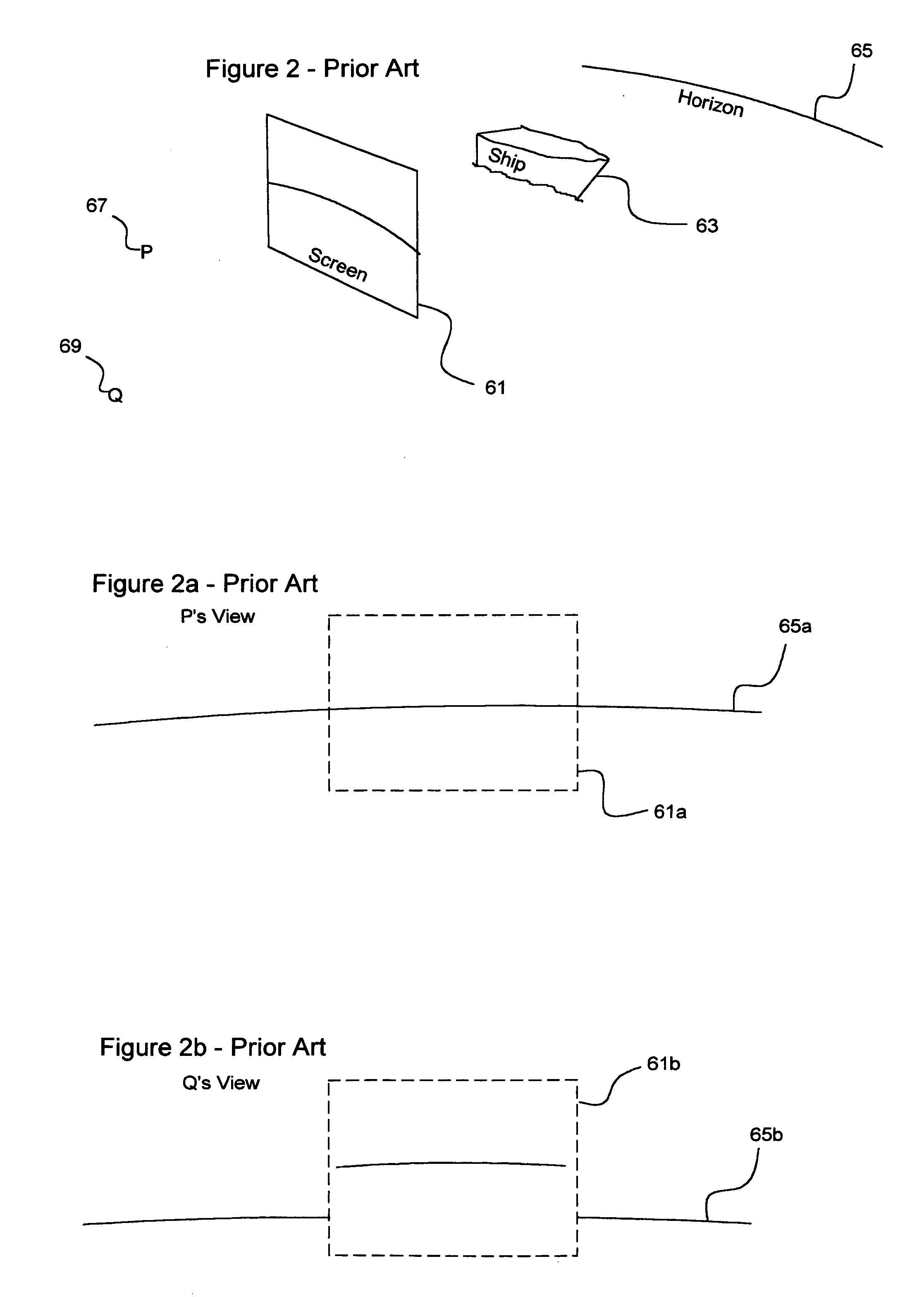
[0032]FIG. 1 prior art, illustrates the shortcomings of prior art of U.S. Pat. No. 5,220,631 and of U.S. Pat. No. 5,307,162. The top half of FIG. 1 illustrates the active camouflage approach used in U.S. Pat. No. 5,220,631. This approach is also described in “JPL New Technology report NPO-20706” August 2000. Asset 134 has a screen or image sender 37 on one side of it. An image receiver 35 on the opposite side of Asset 1 captures an image of the background which is then presented on the image sender. Background point X 32 is represented on the screen as X′36. Note that for an observer at point S 31 this scheme does present a reasonable cloaking apparatus because background points line up with the observer such as X compared with X′. Unfortunately, for observation positions located anywhere other than S, the image sender presents an image that does not correspond with the background. An observer at point T 33 for example can see Asset 1 and can also see back ground point X and backgro...


PUM


Abstract

The invention described herein represents a significant improvement for the concealment of objects and people. Thousands of light receiving segmented pixels and sending segmented pixels are affixed to the surface of the object to be concealed. Each receiving segmented pixel receives colored light from the background of the object. Each receiving segmented pixel has a lens such that the light incident upon it is segmented to form focal points along a focal curve (or plane) according to the light's incident trajectory. In a first embodiment, this incident light is channeled by fiber optics to the side of the object which is opposite to each respective incident light segment. The light which was incident on a first side of the object traveling at a series of respective trajectories is thus redirected and exits on at least one second side of the object according to its original incident trajectory. In this manor, incident light is redirected as exiting light that mimics the incident light's trajectory, wavelength, color, and intensity such that an observer can “see through” the object to the object's background. In a second embodiment, this incident light is segmented according to trajectory, and detected electronically by photo diodes. It is then electronically reproduced on at least one second side of the object by arrayed LEDs. In this manor, incident light is reproduced as exiting light which mimics trajectory, wavelength, color, and intensity such that an observer can “see through” the object to the background. In both embodiments, this process is repeated many times, in segmented pixel arrays, such that an observer looking at the object from any perspective actually “sees the background” of the object corresponding to the observer's perspective. The object having thus been rendered “invisible” to the observer.

Description

CROSS REFERENCE TO RELATED APPLICATIONS[0001]This application is a Continuation-In-Part of application Ser. No. 09 / 757,053 filed Jan. 8, 2001 now abandoned.BACKGROUND FIELD OF INVENTION[0002]The concept of rendering objects invisible has long been contemplated in science fiction. Works such as Star Trek and The Invisible Man include means to render objects or people invisible. The actual achievement of making objects disappear however has heretofore been limited to fooling the human eye with “magic” tricks and camouflage. The latter often involves coloring the surface of an object such as a military vehicle with colors and patterns which make it blend in with its surrounding.[0003]The process of collecting pictorial information in the form of two dimensional pixels and replaying it on monitors has been brought to a very fine art over the past one hundred years. Pryor cloaking devices utilize two dimensional pixels presented on a two dimensional screen. The devices do a poor job of e...

Claims


Application Information

Patent Timeline
IPC IPC(8): G02B27/10G02B6/06G02B26/06
CPCG02B26/06G02B6/06Y10S428/919
Inventor ALDEN, RAY M.
Owner ALDEN RAY M
Why Eureka
Try Eureka