Eureka AIR delivers breakthrough ideas for toughest innovation challenges, trusted by R&D personnel around the world.

Fiber optic premise wiring system

a fiber optic and premise technology, applied in the field of communication, can solve the problems of reducing the carrying capacity of space requirements, limiting the push to move from copper cable to fiber optic cable, and reducing the maintenance cost of electromagnetic/radio frequency interference (emi/rfi)

Inactive Publication Date: 2007-04-17
FINGLER LARRY
View PDF3 Cites 14 Cited by
  • Summary
  • Abstract
  • Description
  • Claims
  • Application Information

AI Technical Summary

Benefits of technology

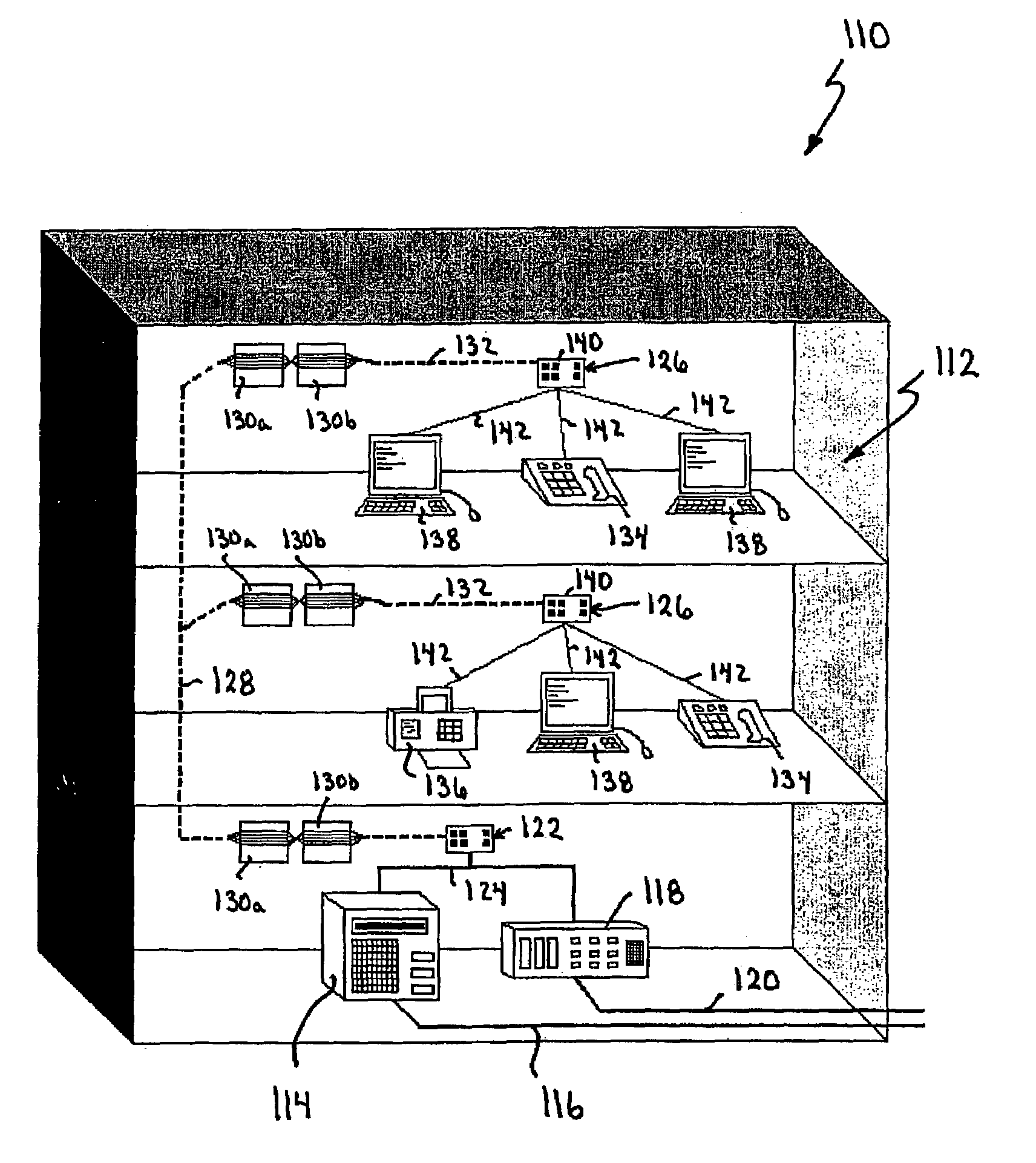
[0019]The present invention provides advantages in that by coupling the communications devices to the backend communications system through fiber optic cable, space requirements for the same carrying capacity as compared with copper cable are reduced. Furthermore by using fiber optic cable to interconnect the communications devices and the backend communications system, communications capacity is increased, maintenance costs and electromagnetic / radio frequency interference (EMI / RFI) are reduced and security is increased due to the fact that it is more difficult to tap into fiber optic cable than copper cable. Also, by running fiber optic cable, safety is increased since the risk of electrical fire is removed.
[0020]The present invention also provides advantages in that longer cable runs between communications devices and the backend communications system can be made without requiring signal amplification components resulting in lower wiring system costs. Also, in cases where the fiber optic cable is installed before it is necessary to convert to fiber optical cable, future conversion costs will be reduced when it becomes necessary to convert to fiber optic cable.
[0021]The present invention provides further advantages in that since the fiber optic cable terminates either at wallboxes or surface mount boxes that provide high quality terminations, installation is facilitated. Also, since the subsystems within the front-end and backend interfaces are modular, they can be easily installed and replaced by technicians with minimal training.

Problems solved by technology

As a result, copper cabling has not been a bottleneck in terms of communications speed and bandwidth and therefore, has not been a deciding factor in forcing a move from copper cable to fiber optic cable.
Further, since current information technology generally does not require fiber optic cable for high or optimum performance and since applications that require fiber optic cable are limited, the push to move from copper cable to fiber optic cable has been limited notwithstanding the advantages associated with fiber optic cable discussed above.
Installing fiber optic cable and components within a premise is a costly investment.
These significant costs have made businesses hesitant to convert to fiber optic cable at this time.

Method used


Image

  • Fiber optic premise wiring system
  • Fiber optic premise wiring system
  • Fiber optic premise wiring system

Examples


Embodiment Construction

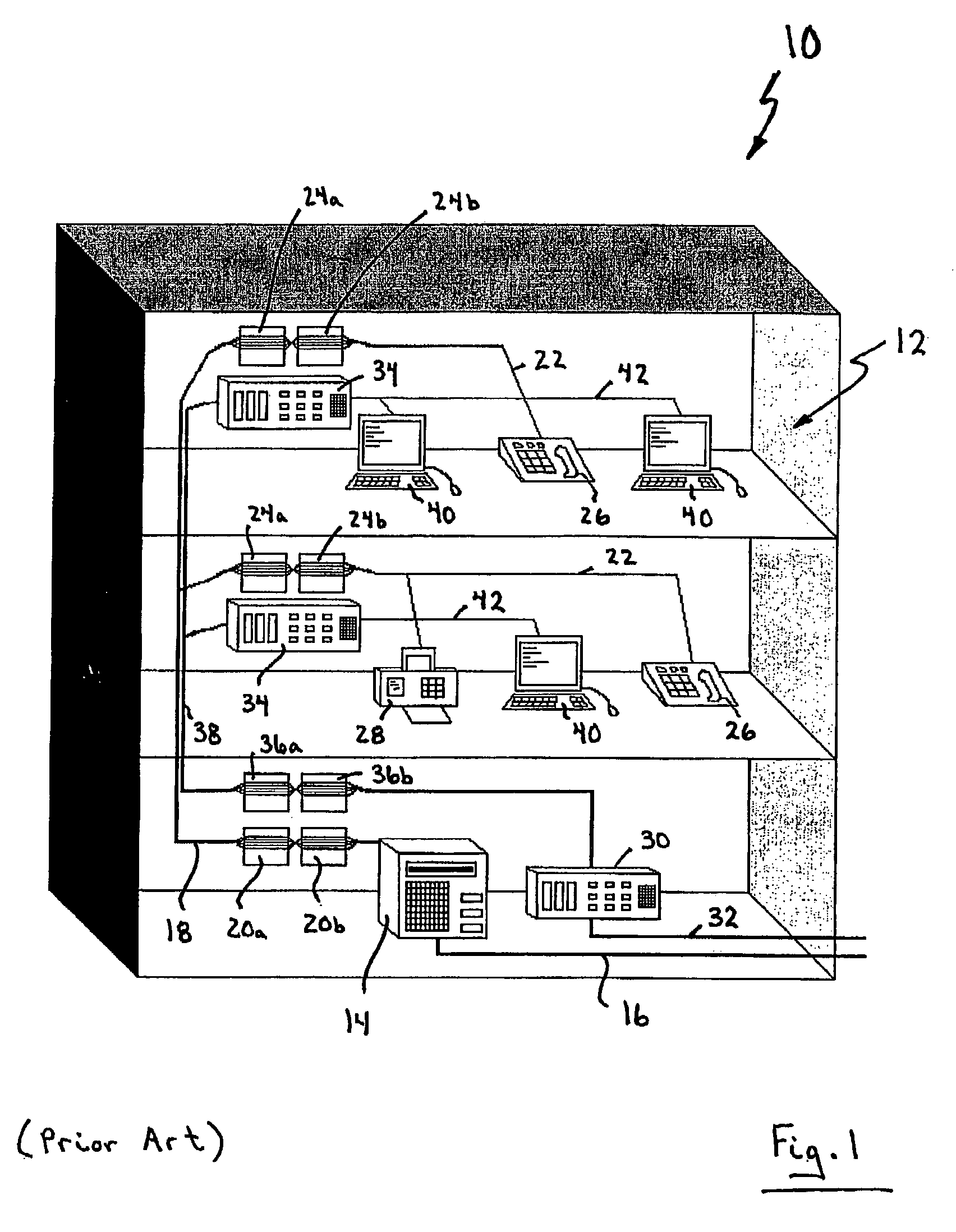
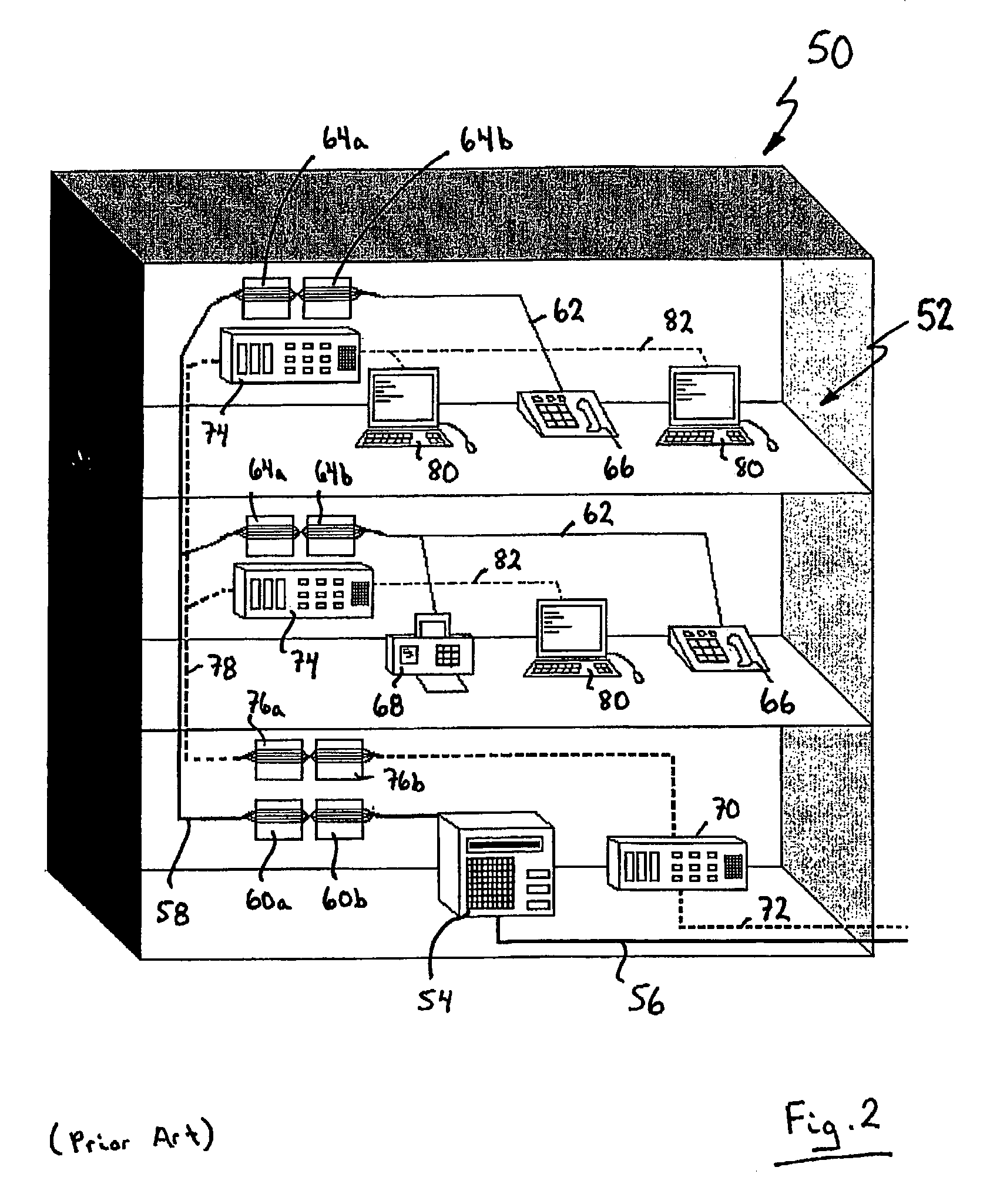
[0033]The present invention relates generally to a fiber optic premise wiring system for communications such as for example voice, data, video etc. Fiber optic cable is used as the communications medium to interconnect communications devices such as telephones, facsimile machines and computer workstations to a backend communications system. To avoid investment in optical component upgrades, modular interfaces are provided between the communications devices and the fiber optic cable as well as between the fiber optic cable and the backend communications system that perform appropriate electrical signal to optical signal to electrical signal conversion. Preferred embodiments of the present invention will be described; however for ease of reference a brief discussion of a conventional copper premise wiring system and a conventional combined copper and fiber optic premise wiring system will firstly be made with reference to FIGS. 1 and 2.

[0034]Turning now to FIG. 1, a multi-story buildi...


PUM


Abstract

A premise wiring system comprises a backend communications system including telephony capabilities and at least one communications device configured for electrical signalling. A signal conversion system acts between the backend communications system and the at least one communications system. The signal conversion system converts electrical signalling being exchanged between the at least one communications device and the backend communications system into optical signalling for transmission over a fiber optic link and reconverts the optical signalling into electrical signalling for delivery to the at least one communications device and the backend communications system.

Description

FIELD OF THE INVENTION[0001]The present invention relates generally to communications and in particular to a fiber optic premise wiring system. The present invention also relates to a system for converting electrical signals to optical signals and back to electrical signals to enable communications devices configured for electrical communications to communicate over a fiber optic link.BACKGROUND OF THE INVENTION[0002]Today's businesses rely significantly on communications and a variety of technologies to access, convey and process information. This need puts a premium on information technology that increases communications speed and bandwidth.[0003]It is well known that fiber optic cable provides significant advantages over its copper cable counterpart. Fiber optic cable has increased capacity and less signal degradation as compared to copper cable, requires less maintenance and is more difficult to tap into. Despite these advantages, most current information technology used for voi...

Claims


Application Information

Patent Timeline
Patent Type & Authority Patents(United States)
IPC IPC(8): H04M11/00H04B10/20
CPCG02B6/43H04B10/27G02B6/4466G02B6/475
Inventor FINGLER, LARRYGALLOWAY, IAINSUTCLIFFE, NADINE
Owner FINGLER LARRY
Why Eureka
Eureka Blog
Learn More