Methods and systems for dynamic, rules-based peg counting

a technology peg counter, which is applied in the field of dynamic and rule-based peg counting methods and systems, can solve the problems of consuming bandwidth, reducing the bandwidth available for other services, and sending copies of all monitored messages across the network of a service provider, so as to reduce the time required to accumulate peg count values, reduce unnecessary bandwidth consumption, and reduce the effect of peg counter creation tim

Inactive Publication Date: 2007-04-17
TEKELEC GLOBAL INC
View PDF7 Cites 3 Cited by
  • Summary
  • Abstract
  • Description
  • Claims
  • Application Information

AI Technical Summary

Benefits of technology

[0013]Because the present invention allows peg counters to be created or modified using a user-friendly graphical user interface and a rules-based language, peg counter creation time is greatly reduced over conventional peg counter implementations that require the user to know the binary or hexadecimal values for all message fields. In addition, because the site collectors can begin using peg counter definitions as soon as they are received and loaded into memory, the time required to activate new or modified peg counters is reduced over hard-coded peg counter implementations that require software upgrades for such changes. Finally, because the present invention distributes peg counter generation among the site collectors, the time required to accumulate peg count values is reduced over implementations in which peg counting is centralized.
[0014]Distributed peg counting also reduces unnecessary bandwidth consumption in a service provider's internal network because entire message copies are not required to be sent to a centralized location. In one implementation of the present invention, the only information that is required to be sent across the service provider's internal network is the accumulator value, the peg counter ID, the origination and destination IDs, a timestamp value indicating the time period to which the peg counter applies, a key type value indicating whether the origination and destination IDs are point codes or other types of identifiers, and a value indicating the total number of octets in the messages that were counted.
[0016]It is another object of the invention to provide a graphical user interface for facilitating the creation of new peg counters.

Problems solved by technology

Another problem associated with some conventional peg count generation systems is that peg counts are generated at a central location, rather than at message collection locations.
Sending copies of all monitored messages across a service provider's network consumes bandwidth and reduces bandwidth available for other services.
In addition, aggregating messages at a central location before generating peg counts greatly increases peg count generation time, because the peg counter application must process messages from all of the message collection locations to create each peg count.

Method used


Image

  • Methods and systems for dynamic, rules-based peg counting
  • Methods and systems for dynamic, rules-based peg counting
  • Methods and systems for dynamic, rules-based peg counting

Examples


Embodiment Construction

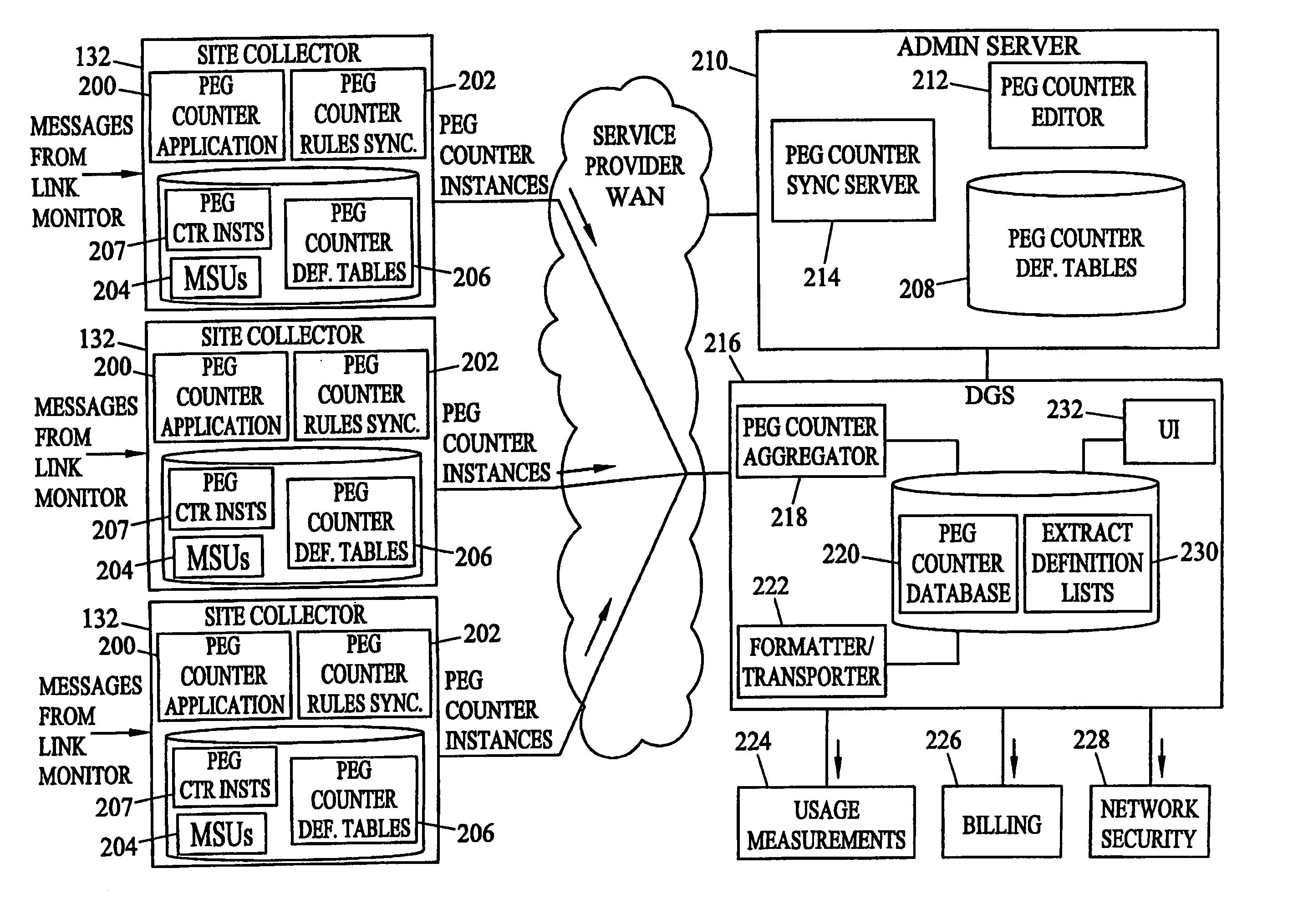
[0027]As discussed above, the present invention includes method and systems for dynamic, rules-based peg counting. FIG. 1 illustrates an exemplary operating environment for dynamic, rules-based peg counting according to an embodiment of the present invention. Referring to FIG. 1, an exemplary telecommunications network includes various entities that generate and route signaling messages. In the illustrated example, the network includes a wireless component 100 for generating and routing signaling messages associated with wireless telecommunications, a wireline component 102 for generating and routing signaling messages associated with wireline communications, and an IP telephony component 104 for generating and routing signaling messages associated with IP telephony communications. Wireless component 100 includes a mobile switching center (MSC) 106, a visitor location register (VLR) 108, a signal transfer point (STP) pair 110, and a home location register (HLR) pair 112. MSC 106 ori...


PUM


Abstract

Methods and systems for dynamic, rules-based peg counting are disclosed. According to one method, a user creates peg counter definitions using a rules-based language accessible via a graphical user interface. The peg counter definitions are downloaded from an administration server to network monitoring site collectors. The site collectors automatically detect the new peg counter definitions and begin using the new peg counter definitions without ceasing existing peg counting. Peg counter software on the site collectors periodically sends peg counter instances to a data gateway server. The data gateway server aggregates the peg counter instances generated by the various site collectors into system wide peg counter instances.

Description

RELATED APPLICATIONS[0001]This application claims the benefit of U.S. provisional patent application No. 60 / 453,233, filed Mar. 10, 2003, the disclosure of which is incorporated herein by reference in its entirety.TECHNICAL FIELD[0002]The present invention relates to methods and systems for collecting network traffic statistics. More particularly, the present invention relates to methods and systems for dynamic, rules-based peg counting.BACKGROUND[0003]In telecommunications signaling networks, it is often necessary to count the number of signaling messages that match user-specified criteria. For example, for usage measurements or billing purposes, it may be necessary to count the number of messages of a particular type originating from a particular source and / or being sent to a particular destination. In order to keep track of such counts, network operators define accumulators in hardware or software associated with signaling link monitoring systems. These accumulators are referred ...

Claims


Application Information

Patent Timeline
Patent Type & Authority Patents(United States)
IPC IPC(8): H04M15/00G06FG08C15/00H04J1/16H04L1/00H04Q3/00
CPCH04M3/36H04M3/365H04M15/43H04M15/58H04Q3/0087H04M2215/0188H04Q2213/13092H04Q2213/13098H04Q2213/13164H04Q2213/13345H04Q2213/13349
Inventor BALDWIN, PATRICIA A.NODEN, DAVID K.WAN, JOSEPH YU-LUNG
Owner TEKELEC GLOBAL INC
Why Eureka
Try Eureka