Boot structure fitting for mechanical joint

a technology for mechanical joints and fittings, applied in the direction of mechanical devices, couplings, rod connections, etc., can solve the problems of axial components, damage to annular lip, and difficulty in assembling the boot, and achieve the effect of stable sealing

Active Publication Date: 2007-04-24
JTEKT CORP
View PDF4 Cites 7 Cited by
  • Summary
  • Abstract
  • Description
  • Claims
  • Application Information

AI Technical Summary

Benefits of technology

[0007]It is an object of the present invention to provide a boot fitting structure for a mechanical joint without difficulty during inserting the axial component in the boot. In order to eliminate difficulty during inserting the axial component in the boot, an annular lip on the inner surface of the boot is formed so that it does not project toward the inner surface of the boot fitting.
[0008]It is a second object of the present invention to provide the boot fitting structure for the axial component to achieve tight fitting to the axial component by elastically deforming of the annular lip.
[0009]It is a third object of the present invention to effectively achieve a concentration of a clamping force to the annular lip by use of a protuberance.

Problems solved by technology

However, it is difficult to assemble the boot by inserting the axial component into the boot due to the annular lip projected from the inner surface of the fitting portion toward center axis of the boot, because the annular lip interferes with the axial component.
Also, the annular lip may be damaged by an edge of the axial component.
However, the small radius top end of the annular lip is easily damaged by the edge of the axial component when the axial component is inserted into the boot.

Method used


Image

  • Boot structure fitting for mechanical joint
  • Boot structure fitting for mechanical joint
  • Boot structure fitting for mechanical joint

Examples


first embodiment

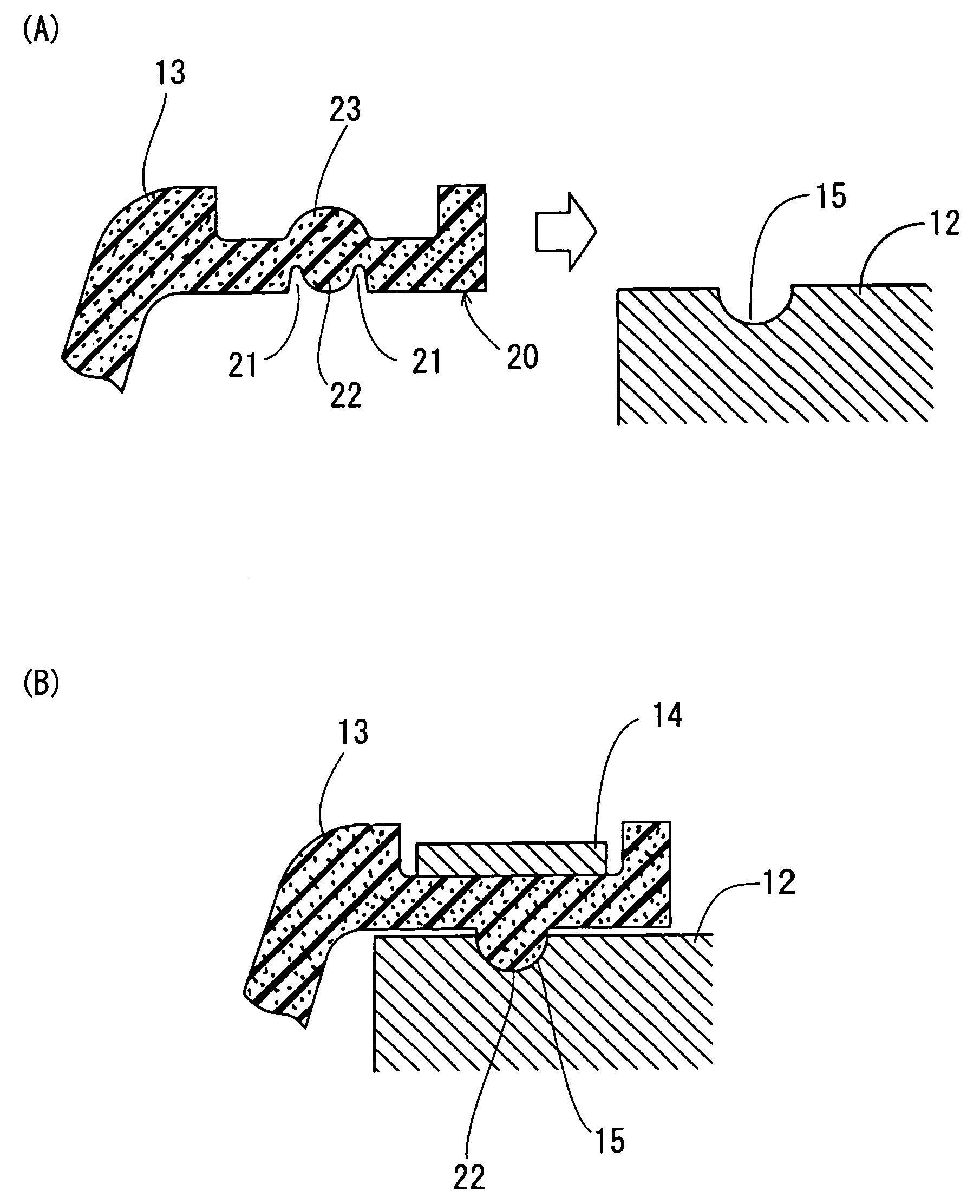
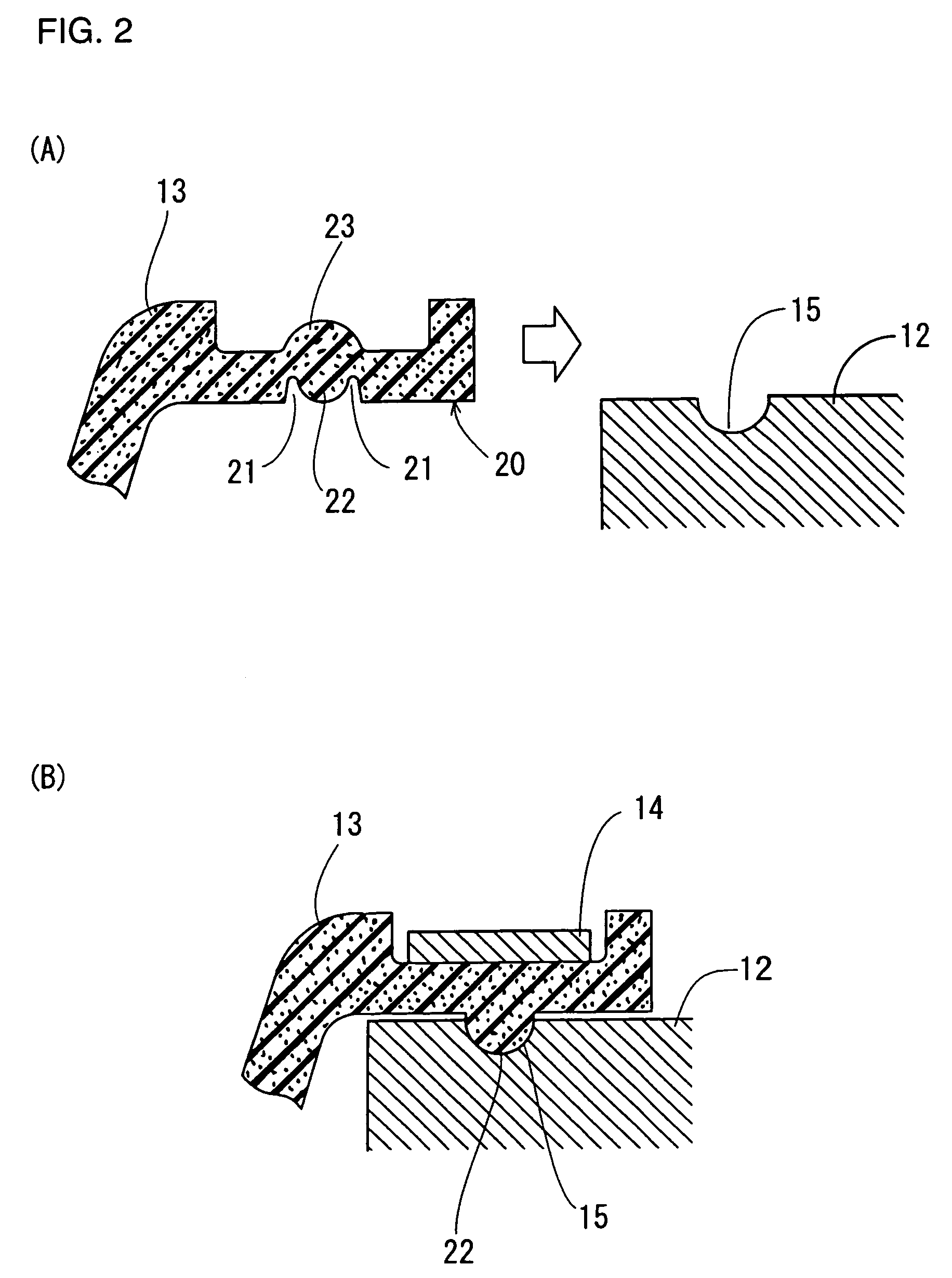
[0028]FIG. 2 (A) and FIG. 2 (B) illustrate first embodiment of the present invention. FIG. 2 (A) shows a detail construction of the boot 13 and a fitting portion of the outer housing 12. There are a pair of annular grooves 21, 21 and an annular lip 22 between the annular grooves 21, 21 on an inner surface 20 of the fitting portion of the boot 13. The annular lip 22 is formed so that the top end of the lip is not projected from the inner surface 20 toward the centerline of the boot. Also, the annular lip 22 is formed to have a small radius top end. An annular protuberance 23 is formed on an opposite side of the annular lip 22 on the outer surface of the boot 13. Therefore, the outer housing 12 can be inserted into the boot 13 without interference between the annular lip 22 and the edge of the outer housing 12. The outer housing 12 has a circumferential groove 15 on outer surface thereof, and the circumferential groove 15 is located at a corresponding longitudinal position to the annu...


PUM


Abstract

A boot fitting structure is fitted onto an axial component to protect it from a dirty environment including outside dust. The boot has a pair of annular grooves and an annular lip between the pair of annular grooves on an inner surface of the boot. The annular lip does not project from an inner surface toward a centerline of the boot. An annular protuberance is provided between the boot and a clamp, through which clamping force from the clamp is concentrated on the annular lip, so that the annular lip is elastically deformed and pushed toward outside of the axial component. Therefore, the axial component can be inserted into the boot without interference between the annular lip and the axial component. Furthermore, the annular lip is free from damage by interference between the annular lip and the axial component.

Description

INCORPORATION BY REFERENCE[0001]The present application claims priority under 35 U.S.C. §119 to Japanese Patent Application No. 2003-284775, filed on Aug. 1, 2003. The contents of that application are incorporated herein by reference in their entirety.BACKGROUND OF THE INVENTION[0002]1. Field of the Invention[0003]The present invention relates to a boot fitting structure between an axial component for a mechanical joint and a boot for protecting the joint from a dirty environment.[0004]2. Description of the Related Art[0005]In a prior art fitting structure between a boot and an axial component, the boot has an annular lip on an inner surface of a fitting portion. The annular lip extends to an inside of the inner surface of the fitting portion. Then the boot is tightly fitted into the axial component and clamped by a clamp from outside of the boot.[0006]However, it is difficult to assemble the boot by inserting the axial component into the boot due to the annular lip projected from t...

Claims


Application Information

Patent Timeline
Patent Type & Authority Patents(United States)
IPC IPC(8): F16D3/84F16J15/52F16J3/04
CPCF16D3/845F16J3/042Y10T403/31F16D3/84F16J3/04
Inventor KASHIWAGI, ISASHIYOSHIDA
Owner JTEKT CORP
Why Eureka
Try Eureka