Thermally or electrically-conductive form-in-place gap filter

a gap filter and thermally or electrically conductive technology, applied in the direction of non-metal conductors, semiconductor/solid-state device details, adhesive processes with surface pretreatment, etc., can solve the problems of increasing complexity of design, increasing the size of devices, and increasing the complexity of circuit designs of modem electronic devices

Active Publication Date: 2007-04-24
PARKER INTANGIBLES LLC
View PDF58 Cites 69 Cited by
  • Summary
  • Abstract
  • Description
  • Claims
  • Application Information

AI Technical Summary

Problems solved by technology

Circuit designs for modem electronic devices such as televisions, radios, computers, medical instruments, business machines, communications equipment, and the like have become increasingly complex.
Although the complexity of the designs has increased, the size of the devices has continued to shrink with improvements in the ability to manufacture smaller electronic components and to pack more of these components in an ever smaller area.
As electronic components have become smaller and more densely packed on integrated boards and chips, designers and manufacturers now are faced with the challenge of how to dissipate the heat which is ohmicly or otherwise generated by these components.
Indeed, it is well known that many electronic components, and especially power semiconductor components such as transistors and microprocessors, are more prone to failure or malfunction at high temperatures.
Thus, the ability to dissipate heat often is a limiting factor on the performance of the component.
For high power circuits and the smaller but more densely packed circuits typical of current electronic designs, however, simple air circulation often has been found to be insufficient to adequately cool the circuit components.
These pockets reduce the overall surface area contact within the interface which, in turn, reduces the heat transfer area and the overall efficiency of the heat transfer through the interface.
Moreover, as it is well known that air is a relatively poor thermal conductor, the presence of air pockets within the interface reduces the rate of thermal transfer through the interface.
The greases and waxes of the aforementioned types heretofore known in the art, however, generally are not self-supporting or otherwise form stable at room temperature and are considered to be messy to apply to the interface surface of the heat sink or electronic component.
Moreover, use of such materials typically involves hand application or lay-up by the electronics assembler which increases manufacturing costs.

Method used


Image

  • Thermally or electrically-conductive form-in-place gap filter
  • Thermally or electrically-conductive form-in-place gap filter

Examples


Embodiment Construction

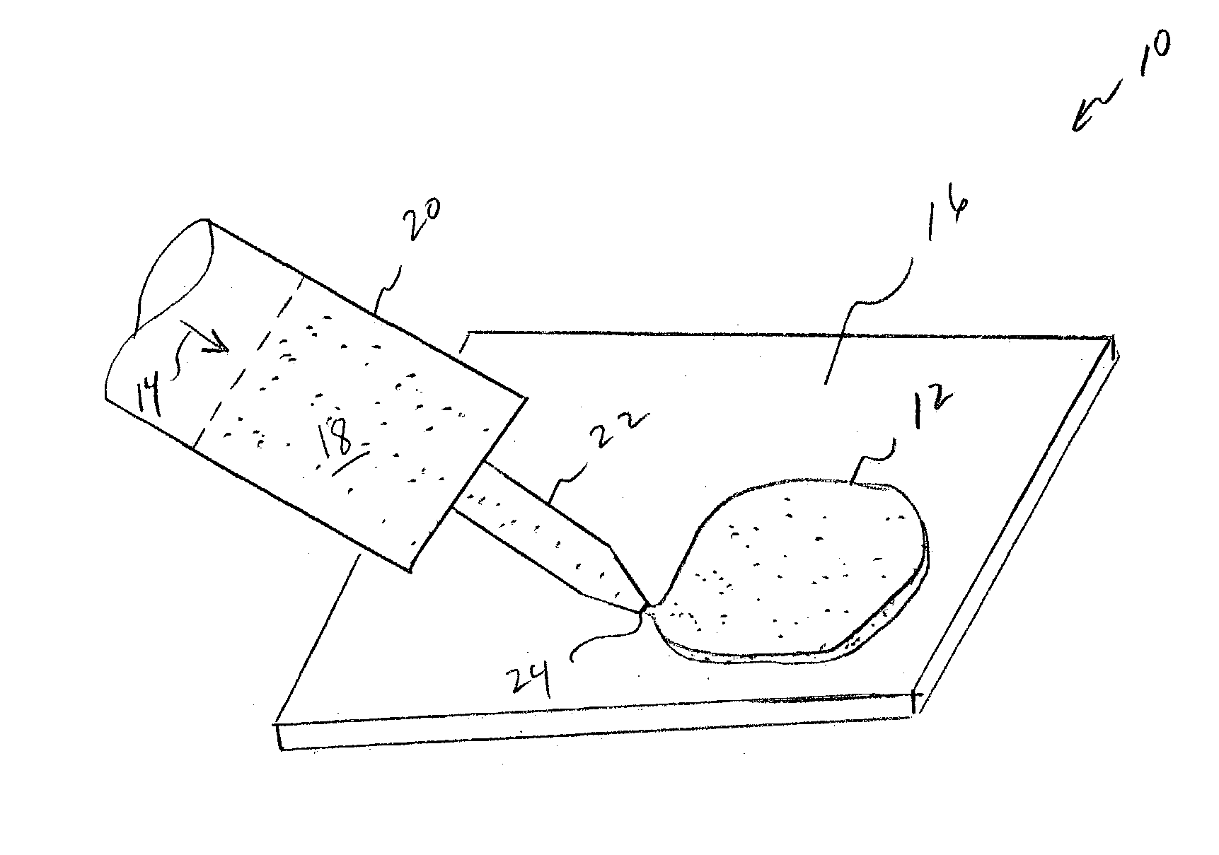
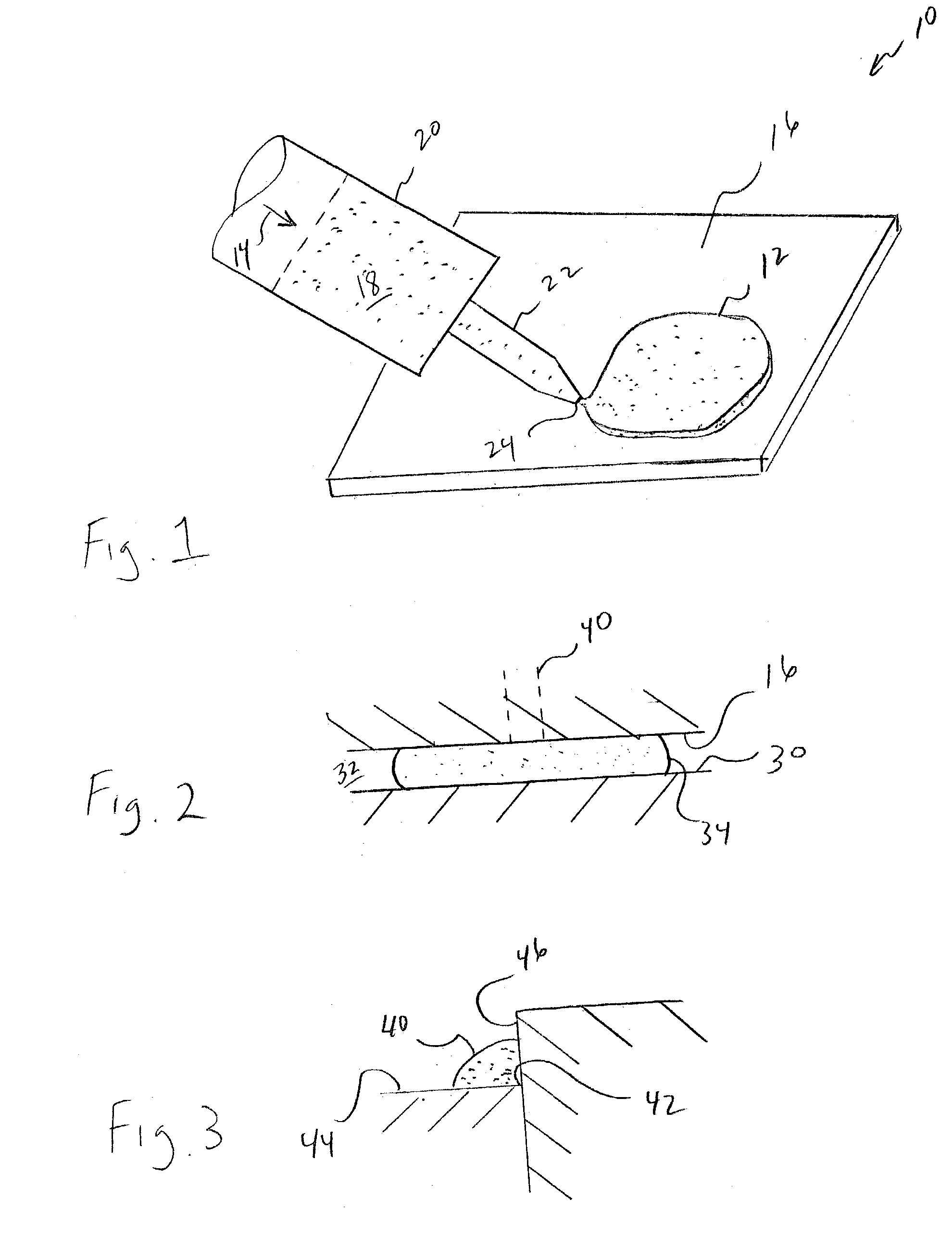
[0027]Certain terminology may be employed in the description to follow for convenience rather than for any limiting purpose. For example, the terms “forward,”“rearward,”“right,”“left,”“upper,” and “lower” designate directions in the drawings to which reference is made, with the terms “inward,”“interior,”“inner,” or “inboard” and “outward,”“exterior,”“outer,” or “outboard” referring, respectively, to directions toward and away from the center of the referenced element, and the terms “radial” or “horizontal” and “axial” or “vertical” referring, respectively, to directions, axes, planes perpendicular and parallel to the central longitudinal axis of the referenced element. Terminology of similar import other than the words specifically mentioned above likewise is to be considered as being used for purposes of convenience rather than in any limiting sense. Further, the term “EMI shielding” should be understood to include, and to be used interchangeably with, electromagnetic compatibility...


PUM

PropertyMeasurementUnit
particle sizeaaaaaaaaaa
thicknessaaaaaaaaaa
frequencyaaaaaaaaaa

Abstract

Application of a thermally and/or electrically conductive compound to fill a thermal and/or EMI shielding gap between a first and a second surface. A supply of a fluent, form-stable compound is provided as an admixture of a cured polymer gel component, and a particulate filler component. An of the compound is dispensed from a nozzle or other orifice under an applied pressure onto one of the surfaces which, when opposed, form the gap, or into the gap formed between the surfaces. The gap is at least partially filled by at least a portion of the dispensed compound.

Description

CROSS-REFERENCE TO RELATED CASES[0001]The present application claims the benefit of the filing date of U.S. Provisional Application Ser. No. 60 / 385,145; filed May 31, 2002, the disclosure of which is expressly incorporated herein by reference.FIELD OF THE INVENTION[0002]The present invention relates broadly to thermally and / or electrically-conductive compounds which may be used as gap fillers or caulks between, for example, the surfaces of an electronic component and another member, such as a heat sink or circuit board, for the conductive cooling and / or the electromagnetic interference (EMI) shielding thereof. More particularly, the invention relates to the application, such as by dispensing through a nozzle, of such a compound which is provided in the form of a cured polymer gel filled with thermally and / or electrically-conductive particulates to one of the surface or into a gap between the surfaces.BACKGROUND OF THE INVENTION[0003]Circuit designs for modem electronic devices such ...

Claims


Application Information

Patent Timeline
Patent Type & Authority Patents(United States)
IPC IPC(8): B05D5/00B05D5/12H01L23/373H01L23/552
CPCH01L23/3737H01L23/552H01L2924/09701Y10T428/263H01L2924/0002H01L2924/3011H01L2924/00Y10T428/31663
Inventor BUNYAN, MICHAEL H.DE SORGO, MIKSA
Owner PARKER INTANGIBLES LLC
Why Eureka
Try Eureka