Lighting device for discharge lamp

a discharge lamp and light device technology, applied in the direction of electric variable regulation, process and machine control, instruments, etc., can solve the problems of difficult temperature balance of electrodes, low stability of discharge, and hardly stable discharge, so as to suppress the generation of flicker of discharge lamps

Inactive Publication Date: 2007-04-24
HARISON TOSHIBA LIGHTING CORP
View PDF5 Cites 25 Cited by
  • Summary
  • Abstract
  • Description
  • Claims
  • Application Information

AI Technical Summary

Benefits of technology

[0007]In connection with this problem, in the lighting device for high-pressure discharge lamp of the above-mentioned patent reference, the stability of the discharge is increased by superposing the current pulse of the same polarity as that of the lamp current on the lamp current at the rear half portion of the lamp current by a means for generating the current pulse connected to the voltage supply source, and thereby intends to suppress the generation of flicker.
[0009]Further, when a high-pressure discharge lamp in which mercury is not sealed is lit, a power applying time at an initial time of lighting is longer than the high-pressure discharge lamp in which the mercury is sealed. Since a large current flows to the high-pressure discharge lamp in which the mercury is not sealed during the period of the power applying time, electrodes are designed to be thick so as not to deform or dissolve the electrodes during this period of time. Therefore, the method for superposing the lamp current in the lighting of the high-pressure discharge lamp in which the mercury is not sealed, is further hardly stabilized in the discharging except the time when the lamp current is superposed, and is said to be a means for easily generating flicker.
[0010]An object of the present invention is to provide a lighting device for high-pressure discharge lamp which suppresses the generation of flicker.
[0012]According to the present invention, the generation of flicker of the discharge lamp can be suppressed.

Problems solved by technology

In a conventional lighting device for lighting a high-pressure discharge lamp by an AC lamp current, it is difficult to take a temperature balance of electrodes due to the presence of a polarity inversion of the lamp current, and stability of discharge is low.
Accordingly, the discharge is hardly stabilized so that flicker occurs.
Further, when a high-pressure discharge lamp in which mercury is not sealed is lit, a power applying time at an initial time of lighting is longer than the high-pressure discharge lamp in which the mercury is sealed.

Method used


Image

  • Lighting device for discharge lamp
  • Lighting device for discharge lamp
  • Lighting device for discharge lamp

Examples


first embodiment

(First Embodiment)

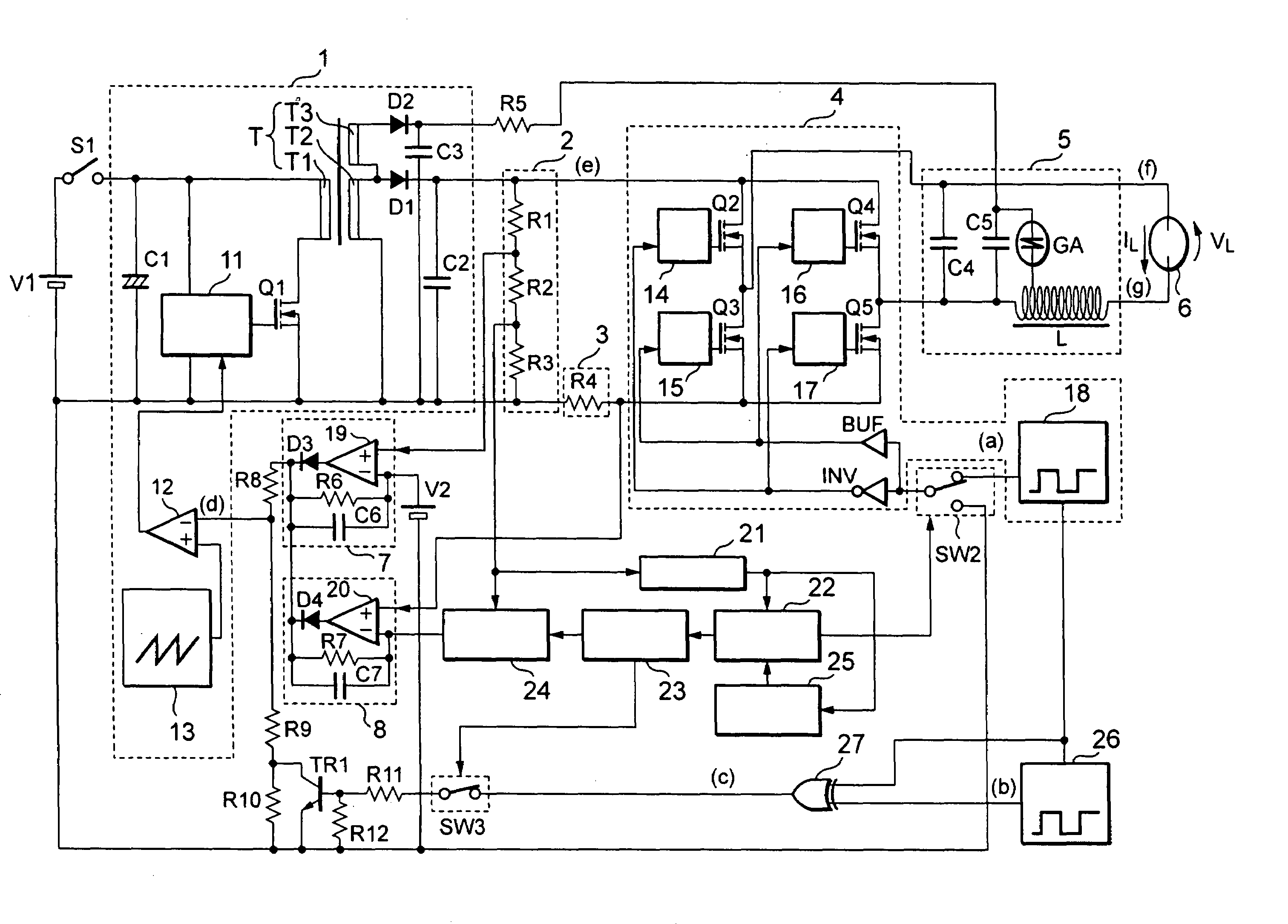
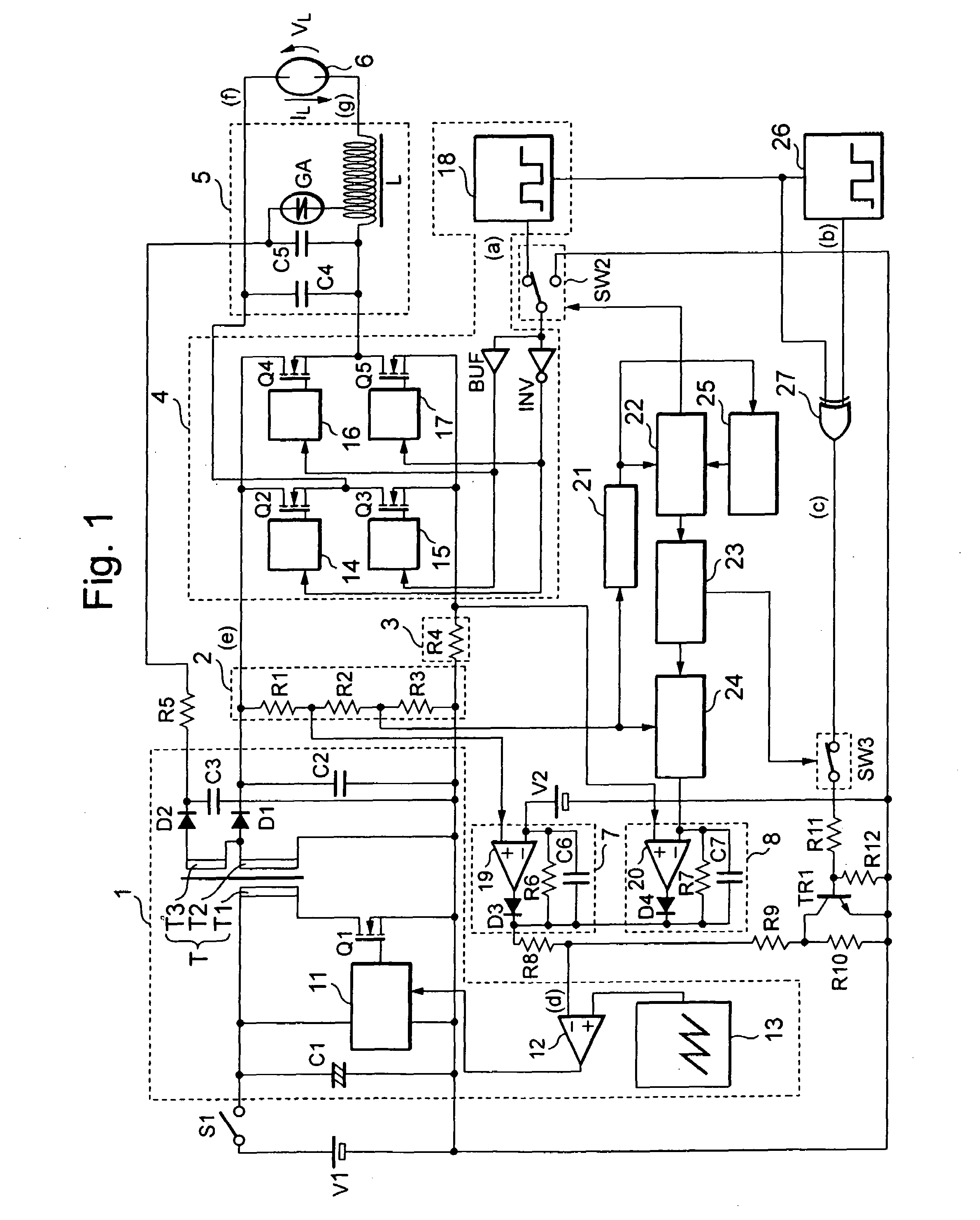
[0027]FIG. 1 shows a circuit configuration of the lighting device for high-pressure discharge lamp according to the first embodiment of the present invention.

[0028]The lighting device comprises a DC power source V1, a switch S1, a DC / DC converter circuit 1, an output voltage detecting circuit 2, an output current detecting circuit 3, a DC / AC inverter circuit 4, an igniter 5, a high-pressure discharge lamp 6 and a control circuit for controlling these.

[0029]In the DC / DC converter circuit 1, a primary side of a transformer T includes a capacitor C1, a switching element Q1, a power MOS drive circuit 11, a PWM comparator 12, a sawtooth-like wave generating circuit 13, and a transformer T1. A secondary side of the transformer T connected to the DC / AC inverter circuit 4 includes a transformer T2, a diode D1 and a capacitor C2, and a secondary side of the transformer T connected to the igniter 5 includes a transformer T3, a diode D2 and a capacitor C3.

[0030]A connecting r...

second embodiment

(Second Embodiment)

[0073]FIG. 4 is a view showing a circuit configuration of a lighting device for high-pressure discharge lamp according to a second embodiment of the present invention. In the respective portions of the second embodiment, the same portions as the respective portions of the lighting device for high-pressure discharge lamp of the first embodiment of FIG. 1 designate the same reference numerals, and the description will be omitted.

[0074]The second embodiment differs from the first embodiment in the following point. Since the second embodiment is not a system for raising the output voltage of the DC / DC converter circuit 1 by regulating the duty ratio of the switching element Q1, only a signal from the differential amplifying circuit 7 or the differential amplifying circuit 8 affects the inverting input terminal of the PWM comparator 12.

[0075]Furthermore, a control circuit 28 including a function of the switch SW2 is connected instead of the buffer BUF, the inverter INV...

third embodiment

(Third Embodiment)

[0098]The present invention can be applied to, for example, a lighting device for a single-ended mold high-pressure discharge lamp, in which the temperature of the electrodes of the discharge lamp differ, such as a headlight of the automobile. Such an embodiment of the present invention will be described.

[0099]Generally, the single-ended mold high-pressure discharge lamp 30, such as a headlight of an automobile, has a structure as shown in FIG. 9. That is, metal foils 33a, 33b are respectively connected to electrodes 32a, 32b provided oppositely in a light emitting tube 31, and external lead wires 34a, 34b for applying a power from an outside source are respectively connected to these metal foils 33a, 33b. In the single-ended mold high-pressure discharge lamp of such a structure, as shown in FIG. 9, a heat is positively dissipated in a direction of a base, however, since the radiation of heat in an opposite direction is remarkably small as compared with the former ...


PUM


Abstract

A lighting device for high-pressure discharge lamp for lighting the high-pressure discharge lamp by lowering or raising a DC voltage applied to an input side by a DC / DC converter circuit, then converting the DC power into an AC power by a DC / AC inverter circuit, supplying the AC power to the high-pressure discharge lamp and lighting the high-pressure discharge lamp, wherein when the polarity of the current of the high-pressure discharge lamp lit by the substantially rectangular wave is inverted, the output voltage of the DC / DC converter circuit is set to 1.5 times or more as large as the voltage at the stable lighting time of the high-pressure discharge lamp.

Description

CROSS-REFERENCE TO RELATED APPLICATIONS[0001]The present invention contains subject matter related to Japanese Patent Application JP 2004-159010 filed on May 28, 2004, and Japanese Patent Application JP 2005-106257 filed on Apr. 1, 2005, in the Japanese Patent Office, the entire contents of which being incorporated herein by reference.BACKGROUND OF THE INVENTION[0002]1. Field of the Invention[0003]The present invention relates to a lighting device for high-pressure discharge lamp used to light a headlight for an automobile.[0004]2. Description of the Related Art[0005]A conventional lighting device for high-pressure discharge lamp is connected at its input side of a voltage supply source for generating a DC current to a power source for supplying a voltage, and connected at its output side of the voltage supply source to a commutator for converting a DC current into an AC current, and lights the high-pressure discharge lamp connected to the output side by an AC lamp current. Also, a ...

Claims


Application Information

Patent Timeline
Patent Type & Authority Patents(United States)
IPC IPC(8): H05B37/02H05B41/16H05B39/04H05B41/288
CPCH05B41/2886Y02B20/202Y02B20/00H05B41/26
Inventor ISHIZUKA, AKIO
Owner HARISON TOSHIBA LIGHTING CORP
Why Eureka
Try Eureka