Increasing force transmissibility for tactile feedback interface devices

a technology of tactile feedback and transmittance, which is applied in the direction of static indicating devices, instruments, sport apparatus, etc., can solve the problems of inability to accurately measure, force is not as crisp, precise, or controllable, and the transmittance of tactile feedback is limited. , to achieve the effect of increasing the transmissibility of inertial forces

Inactive Publication Date: 2007-04-24
IMMERSION CORPORATION
View PDF72 Cites 95 Cited by
  • Summary
  • Abstract
  • Description
  • Claims
  • Application Information

AI Technical Summary

Benefits of technology

[0007]The present invention is directed to increasing the transmissibility of inertial forces produced by an inertial actuator on the housing of a tactile feedback interface device.
[0009]The compliant suspension can include in some embodiments at least one spring member, such as a leaf spring, diaphragm, or spring beams integrated with the housing of the interface device. A damping member, such as foam, oil, etc. can also be coupled between the actuator and housing to reduce a peak magnitude of the output forces. The host computer can be a video game console, where the graphical environment is a game, and where the periodic inertial forces are correlated with events and interactions in the game. The motor can be a rotary motor with an eccentric mass coupled to its rotating shaft, or an actuator that moves oscillates an inertial mass linearly.
[0010]The present invention advantageously allows the output of increased magnitude inertial forces such as vibrations to the housing of an interface device without having to increase the power to the actuators causing the forces. This increase in inertial force magnitude allows harmonically-driven inertial masses to be more effective at producing compelling tactile sensations to a user of the interface device, and allows all inertial tactile devices to be more efficient in delivering tactile sensations.

Problems solved by technology

Therefore, haptic feedback interface devices have been typically limited to simpler embodiments that provide more limited forms of haptic feedback.
One problem with existing tactile controllers is that they are limited in the magnitude of forces output to the user.
Devices driving a motor and mass in only one rotational direction tend to provide greater amplitude forces in an inertial tactile device, but the forces are not as crisp, precise, or controllable as forces output by a harmonically (bidirectional) driven motor and mass.
The drawback of the harmonically-driven mass, or low power tactile devices, is that the forces are often not strong enough to be compelling to the user, especially in applications such as games or virtual reality.

Method used


Image

  • Increasing force transmissibility for tactile feedback interface devices
  • Increasing force transmissibility for tactile feedback interface devices
  • Increasing force transmissibility for tactile feedback interface devices

Examples


embodiment 250

[0059]FIG. 7 shows a diagrammatic illustration of an embodiment 250 of an inertial tactile feedback system of the present invention, where an eccentric mass 252 or other inertial device (i.e. a linkage or other mechanism for providing mass, e.g., a linkage providing one particular vibration response in one direction and a different response in the other direction of rotation) is mounted on the rotatable shaft 254 of an actuator 256 such as a motor. The mass 252 rotates about an axis A. The motor housing is rigidly coupled to a motor bracket 258, and the motor bracket 258 is compliantly coupled to the device housing 260 (suspended) by one or more spring elements 262. The device housing is held or otherwise physically contacted by the user.

[0060]The spring elements 262 can take a variety of different forms, including helical springs, leaf springs, compliant members, diaphragms, or other types of elements. The compliance of the springs have been chosen such that the resonance frequency...

embodiment 300

[0063]FIG. 8 illustrates an example of a specific embodiment 300 of the invention, in which a compliance mechanism 301 is formed as a single piece with the housing of the device. A rotary motor 302 having an eccentric mass 304 is rigidly coupled to a motor bracket 306. The motor bracket 306 is coupled to the housing 308 of the device by spring beams 310, where the spring beams 310 are preferably integrated in the same unitary material as the bracket 306 and the housing 308. This allows the entire suspension, including beams 310 and bracket 306, to be molded as a single piece with the housing 308, thus greatly reducing manufacturing and assembly cost. The housing 308, bracket 306, and spring beams 310 can be made of a plastic having the desired compliance, for example. The spring beams 310 can be designed at the proper width and length to provide the desired spring constant and amplification range to inertial forces produced by the actuator. Furthermore, flex joints can be provided a...
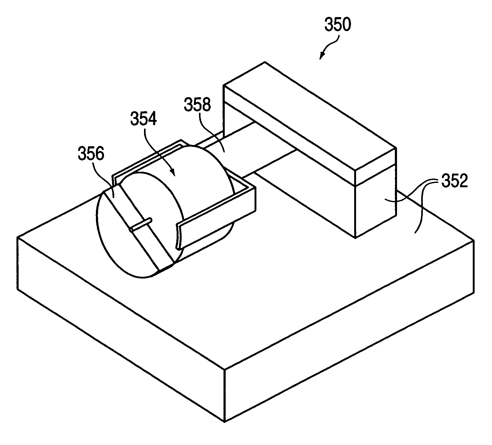
embodiment 350

[0064]Another embodiment 350 is shown in FIG. 9. A base mass 352 is approximately matched to the mass of a gamepad controller. A motor 354 having an ERM 356 is coupled to the base 352 by a leaf spring 358 to provide the compliance between motor and housing. This prototype was placed on a foam layer so that an accelerometer attached to the base could be used to measure the transmitted force. In the test, the base was rotated vertically so that the motor vibrations acted against the leaf spring's most compliant axis.

[0065]As expected, when the motor was harmonically driven with a sine function, the magnitude of the housing acceleration could be maximized by altering the leaf spring suspension stiffness. For instance, by tuning spring stiffness to maximize peak output force at 80 Hz resonance, it was possible to boost the acceleration measured on the base everywhere below that frequency, thus providing higher-magnitude vibrations. This process was repeated for several natural frequenci...


PUM


Abstract

Method and apparatus for increasing the transmissibility of inertial forces produced by an inertial actuator on the housing of a tactile feedback interface device. A tactile interface device, coupled to a host computer, outputs tactile sensations to a user based on interactions and events occurring in a displayed graphical environment. An actuator produces periodic inertial forces, such as vibrations, and a compliant suspension couples the actuator to the device housing. A compliance of the suspension is selected such that the suspension magnifies the periodic inertial forces for a particular frequency range of the inertial forces. The magnified inertial forces are transmitted to the housing to be felt by the user.

Description

CROSS REFERENCE TO RELATED APPLICATIONS[0001]This application is a continuation of U.S. application Ser. No. 09 / 675,995, filed on Sep. 29, 2000, now U.S. Pat. No. 6,680,729 entitled “Increasing Force Transmissibility for Tactile Feedback Interface Devices” and also claims the benefit of Provisional Patent Application No. 60 / 157,206, filed Sep. 30, 1999 by Shahoian et al., entitled “Increasing Vibration Transmissibility in Vibrotactile Controllers by Tuning Suspension Compliance,” each of which is incorporated herein by reference in their entirety.BACKGROUND OF THE INVENTION[0002]The present invention relates generally to tactile feedback human-computer interface devices, and more specifically to enhancing inertial tactile feedback in such interface devices.[0003]Computer devices are widely used for entertainment activities such as playing games. Currently, popular gaming computer devices include game consoles connected to a home television set, such as the Nintendo® 64 from Nintendo...

Claims


Application Information

Patent Timeline
Patent Type & Authority Patents(United States)
IPC IPC(8): G09G5/00A63F13/06G06F3/00G06F3/01
CPCA63F13/06G06F3/016A63F2300/1037A63F2300/1043A63F13/812A63F13/245A63F13/803A63F13/818A63F2300/8011A63F2300/8017A63F2300/8035A63F13/285
Inventor SHAHOIAN, ERIK J.MARTIN, KENNETH M.
Owner IMMERSION CORPORATION
Why Eureka
Try Eureka