Unlock instant, AI-driven research and patent intelligence for your innovation.

Disk drive with phase-quadrature servo pattern and demodulated position error signal insensitive to timing and phase-misalignment errors

a phase-quadrature servo pattern and demodulated position error technology, applied in the direction of magnetic recording, alignment of track following on disks, instruments, etc., can solve the problems of phase-misalignment errors and the demodulator does not account for clock errors in reading the servo pattern

Inactive Publication Date: 2007-04-24
HITACHI GLOBAL STORAGE TECH NETHERLANDS BV
View PDF17 Cites 22 Cited by
  • Summary
  • Abstract
  • Description
  • Claims
  • Application Information

AI Technical Summary

Benefits of technology

"The invention is a disk drive with a special pattern on the servo tracks that helps the drive detect its position. The servo signals are made up of two bands, each with a different pattern that is phase-shifted from the other. The demodulator calculates the amplitudes of these signals and removes errors caused by clock and phase misalignment. This results in a more accurate servo signal that is used to control the actuator in the disk drive. The technical effect of this invention is to improve the accuracy and reliability of disk drives."

Problems solved by technology

However, the conventional demodulator does not account for clock errors in reading the servo pattern and for phase-misalignment errors between the two phase-shifted patterns.

Method used


Image

  • Disk drive with phase-quadrature servo pattern and demodulated position error signal insensitive to timing and phase-misalignment errors
  • Disk drive with phase-quadrature servo pattern and demodulated position error signal insensitive to timing and phase-misalignment errors
  • Disk drive with phase-quadrature servo pattern and demodulated position error signal insensitive to timing and phase-misalignment errors

Examples


Embodiment Construction

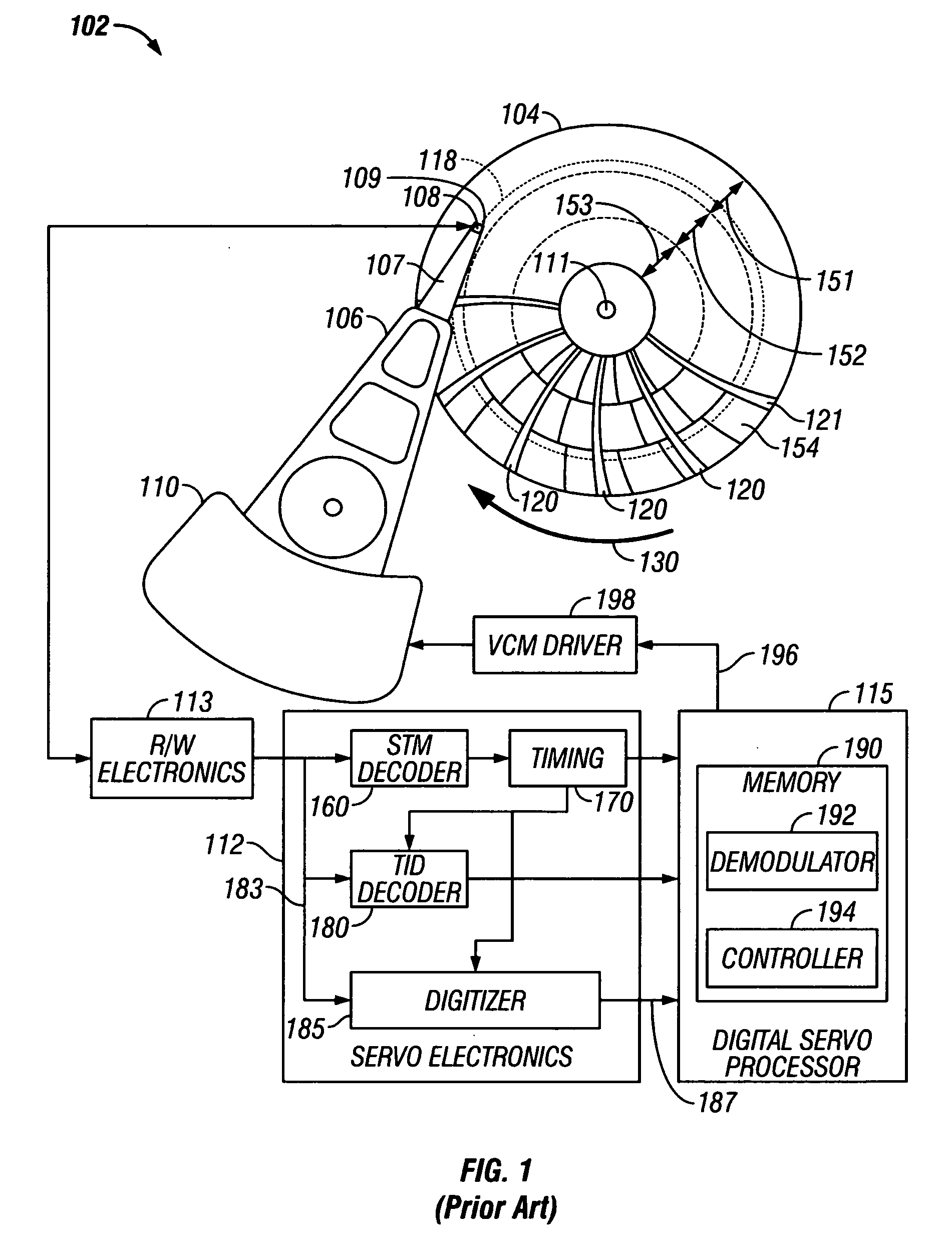
[0020]FIG. 1 is a block diagram of a disk drive according to the present invention. The disk drive uses servo positioning information located in angularly-spaced servo sectors for positioning the read / write heads. The disk drive, generally designated as 102, includes data recording disk 104, a voice coil motor (VCM) 110 as the actuator, an actuator arm 106, a suspension 107, a head carrier or air-bearing slider 108, a data recording transducer 109 (also called a head, recording head or read / write head), read / write electronics 113, servo electronics 112, and servo control processor 115.

[0021]The recording head 109 may be an inductive read / write head or a combination of an inductive write head with a magnetoresistive read head and is located on the trailing end of slider 108. Slider 108 is supported on the actuator arm 106 by a suspension 107 that enables the slider to “pitch” and “roll” on an air-bearing generated by the rotating disk 104. Typically, there are multiple disks stacked ...


PUM

PropertyMeasurementUnit
circumferential widthaaaaaaaaaa
widthaaaaaaaaaa
magnetic transitionsaaaaaaaaaa

Abstract

A magnetic recording disk drive uses a phase-quadrature position-error-signal (PES) pattern and a servo signal demodulator that is insensitive to clock errors and phase-misalignment errors. The disk has angularly-spaced servo sectors, with each servo sector having radially-spaced servo tracks that contain a phase-quadrature pattern of servo blocks. A first band in each servo sector contains two generally like patterns radially-spaced in the servo track with the second pattern phase-shifted 90 degrees along-the-track from the first pattern. A second band in each servo sector is spaced along-the-track from the first band and also has two patterns like those in the first band, but with the phase shift of the second pattern being in the opposite direction to the phase shift of the second pattern in the first band. The demodulator calculates the true amplitudes of the servo signal from the measured amplitudes of the servo signals from each band to thereby remove clock errors and phase-misalignment errors.

Description

BACKGROUND OF THE INVENTION[0001]1. Field of the Invention[0002]This invention relates generally to magnetic recording hard disk drives, and more particularly to disk drives that use phase-quadrature servo patterns as part of the head-positioning servo control system.[0003]2. Description of the Related Art[0004]In a magnetic recording hard disk drive, the read / write head is moved across the data tracks of the rotating disk and maintained on the data tracks by an actuator, typically a rotary voice-coil-motor (VCM) actuator. The head detects a position-error-signal (PES) pattern from angularly-spaced servo sectors on the disk and generates a servo signal that is demodulated to provide the PES. The disk drive servo control system receives the PES and generates a control signal to the actuator to maintain the head on track and move it to the desired track for reading and writing of data. Each read / write head is attached to the end of a head carrier or air-bearing slider that rides on a ...

Claims


Application Information

Patent Timeline
Patent Type & Authority Patents(United States)
IPC IPC(8): G11B5/596
CPCG11B5/59688
Inventor BANDIC, ZVONIMIR Z.MOSER, MICHAEL A.
Owner HITACHI GLOBAL STORAGE TECH NETHERLANDS BV