Method and apparatus for positioning an optical fiber

a technology of optical fiber and positioning device, applied in the field of optical fiber positioning device, can solve the problems of loss or attenuation of signal, physical damage that may be present at the end face, lateral displacement or offset of optical fiber of two mated connectors, etc., and achieve the effect of reducing the amount of optical fiber bending

Inactive Publication Date: 2007-04-24
CORNING OPTICAL COMM LLC
View PDF21 Cites 6 Cited by
  • Summary
  • Abstract
  • Description
  • Claims
  • Application Information

AI Technical Summary

Benefits of technology

[0012]This invention addresses the above needs by providing a optical fiber positioning apparatus and method that reduces the amount of optical fiber bending caused when an optical fiber is pushed in a particular direction in the passageway. Consequently, the position of the optical fiber is substantially straight for an appreciable distance back from the end face of the ferrule so that the optical fiber is still in the desired position in the passageway even after polishing of the optical fiber and ferrule. As used herein, the term “passageway” includes encapsulated passageways (e.g., bores and similar structures), non-encapsulated passageways (e.g., channels, grooves, and similar structures), and combinations thereof. As used herein, the term “ferrule” includes cylindrical and non-cylindrical ferrules housing a single fiber, such as, for example, SC, LC, MU, BLC and other similar ferrules.
[0013]In accordance with one embodiment, a method of positioning an optical fiber in a passageway of a ferrule involves applying a fluid adhesive in the passageway of the ferrule, and subsequently inserting an optical fiber into the passageway of the ferrule such that an end portion of the optical fiber projects out from the passageway beyond the end face of the ferrule, the optical fiber having a diameter less than that of the passageway. A force F is imposed on the end portion of the optical fiber projecting from the ferrule, in a direction generally orthogonal to the longitudinal axis of the passageway, the force having sufficient magnitude to overcome viscosity of the fluid adhesive and to position the optical fiber in the passageway as to compensate for eccentricity of the passageway such that the optical fiber position relative to the passageway is substantially straight for a predetermined distance. In contrast to prior methods, bowing of the optical fiber in the passageway is minimized by imposing the force F at a distance D from the end face such that the resulting moment (F·D) exerted on the optical fiber maintains the axis of the optical fiber straight within at least about 0.025 μm for a distance of at least about 100 μm from the end face into the passageway. Accordingly, up to about 100 μm of material (ferrule, optical fiber, and adhesive) can be removed during polishing and yet the optical fiber position after polishing will be within at least about 0.025 μm of the same position before polishing.

Problems solved by technology

Other factors that can affect the loss or attenuation of signal at a fiber-to-fiber interconnection include: index of refraction mismatch, mode field radius mismatch, the shape and finish of the end faces, and physical damage that may be present at the end faces.
Lateral displacement or offset of the optical fibers of two mated connectors can result from various causes.
Although a general method of pushing an optical fiber to one side of the passageway is thus known, the prior art does not provide any guidance on how best to accomplish the method.
However, as illustrated in FIG. 1, which is shown in exaggerated detail for illustrative purposes, the force exerted on the optical fiber to push it to one side of the passageway can cause the optical fiber to bend or bow.
In addition, attenuation is caused by the angular misalignment of the mating passageways.

Method used


Image

  • Method and apparatus for positioning an optical fiber
  • Method and apparatus for positioning an optical fiber
  • Method and apparatus for positioning an optical fiber

Examples


Embodiment Construction

[0031]This invention now will be described more fully hereinafter with reference to the accompanying drawings, in which preferred embodiments of the invention are shown. This invention may, however, be embodied in many different forms and should not be construed as limited to the embodiments set forth herein; rather, these embodiments are provided so that this disclosure will be thorough and complete, and will fully convey the scope of the invention to those skilled in the art. Like numbers refer to like elements throughout.

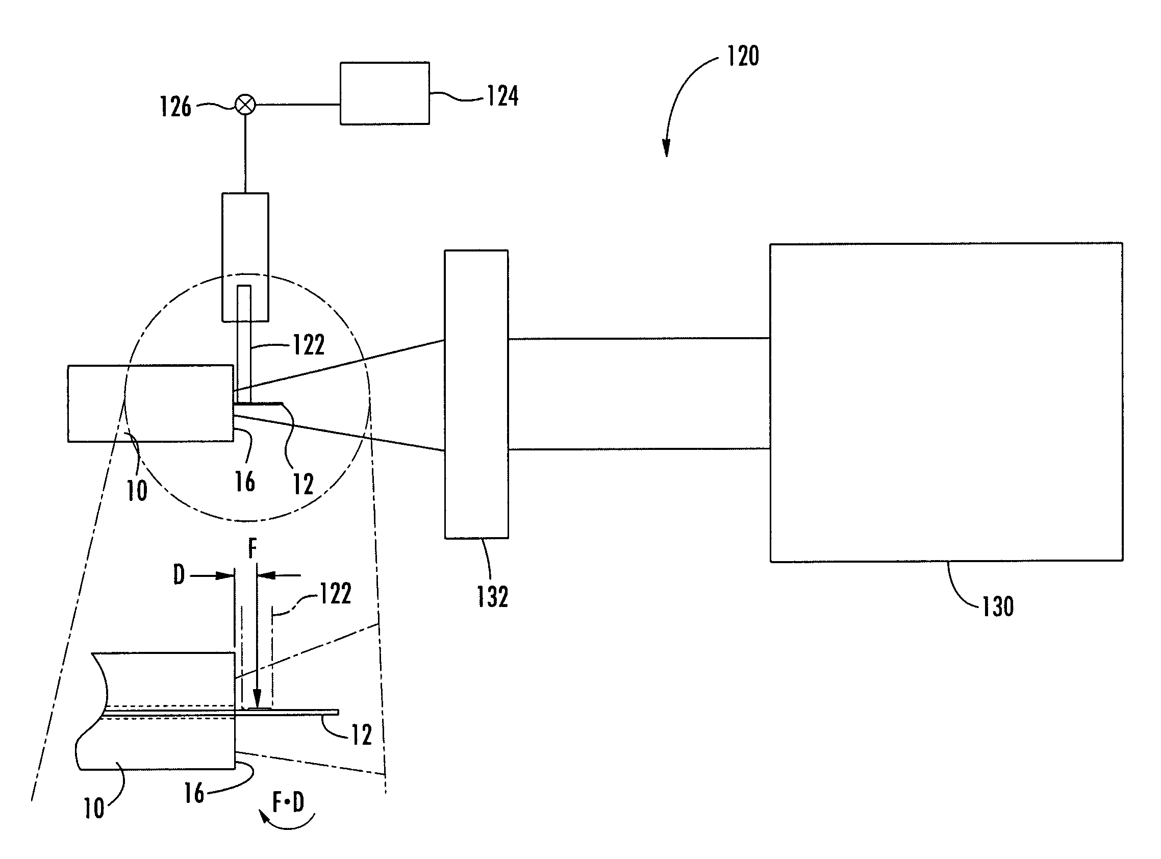
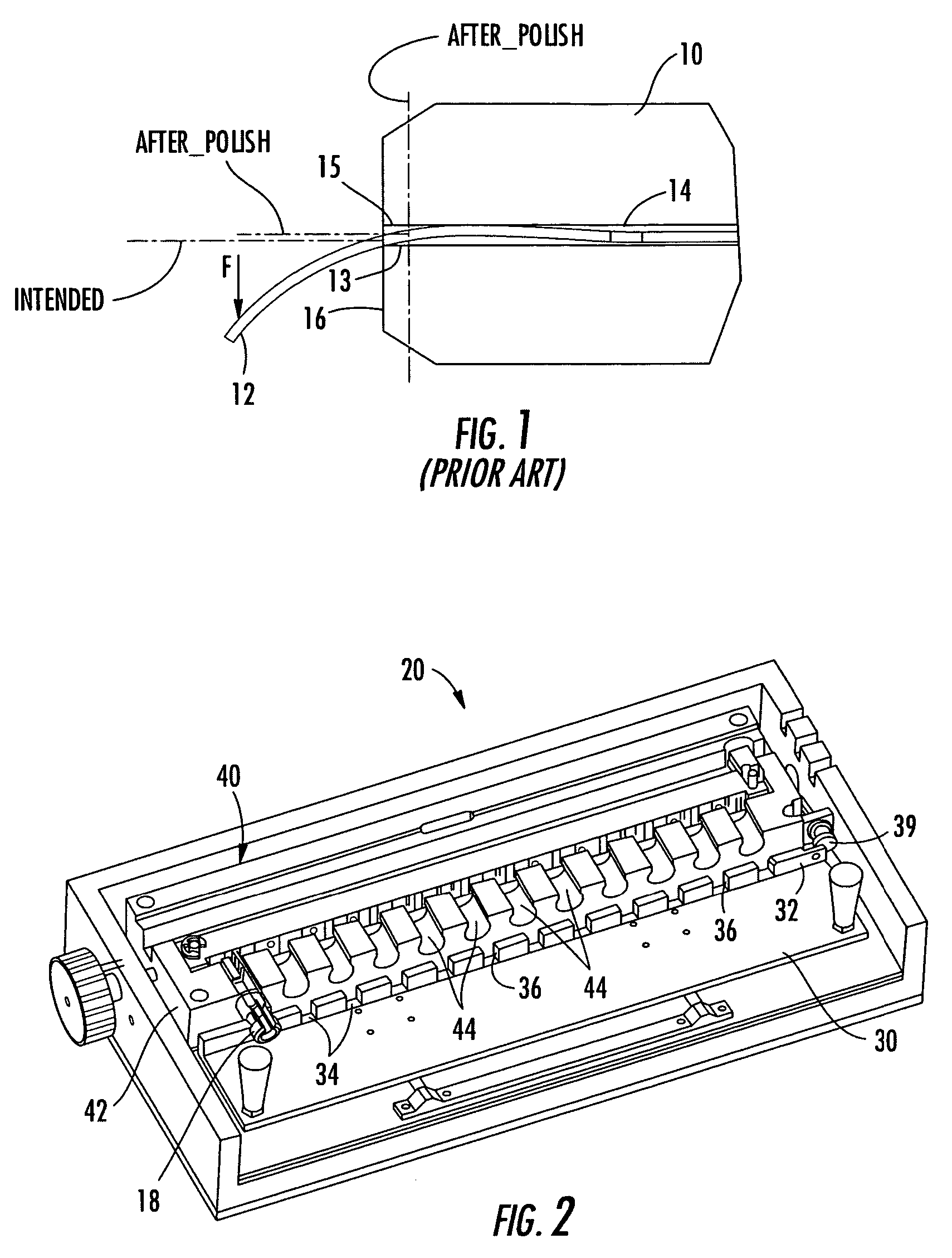
[0032]FIG. 1, as previously discussed, illustrates the effect of directing an end portion of an optical fiber 12 to desired position in a bore 14 of a ferrule 10. The optical fiber 12 is shown installed in the bore 14 of the ferrule 10. A force F is applied to the optical fiber 12, downward in FIG. 1, to push the optical fiber 12 to a lower side 13 of the bore 14. The optical fiber 12 is thus subjected to a bending moment that causes the optical fiber 12 to bend ...


PUM


Abstract

Eccentricity of a optical fiber installed in a passageway of a ferrule is minimized by imposing a force on the end of the optical fiber projecting from the passageway at the ferrule end face to push the optical fiber to a desired position in the passageway, prior to curing an adhesive used for fixing the optical fiber in the passageway, so as to compensate for eccentricity of the passageway. In one embodiment, the force is imposed on the optical fiber by hanging a weight on the optical fiber. In another embodiment, the force is imposed on the optical fiber by using a pressurized jet of fluid. The point of application of the force, the magnitude of the force, and the viscosity of the adhesive are selected such that minimal optical fiber bending occurs, thereby assuring that the optical fiber is positioned at the desired position in the passageway for an appreciable distance from the ferrule end face along the passageway.

Description

[0001]This application is a divisional of U.S. patent application Ser. No. 10 / 003,334 filed Oct. 31, 2001 now U.S. Pat. No. 6,672,772.FIELD OF THE INVENTION[0002]This invention relates generally to method and apparatus for positioning an optical fiber. More particularly, this invention relates to a method and apparatus for positioning an optical fiber in a passageway formed through a ferrule of an optical fiber connector in such a way as to compensate for eccentricity of the passageway relative to the longitudinal axis of the ferrule such that the optical fiber position relative to the passageway is substantially straight for a predetermined distance.BACKGROUND OF THE INVENTION[0003]The transmission of communication signals for voice, video, data, and the like, is increasingly accomplished using optical fibers because of the high bandwidth and throughput capabilities they offer in comparison with conventional electrical conductors. Unlike connections for electrical conductors, howev...

Claims


Application Information

Patent Timeline
Patent Type & Authority Patents(United States)
IPC IPC(8): G02B6/38G02B6/25
CPCG02B6/25G02B6/3843G02B6/3861
Inventor GIMBEL, BRIAN J.LUTHER, JAMES P.THEUERKORN, THOMASTRAN, HIEU V.CHILDERS, DARRELLKNECHT, DENNIS M.
Owner CORNING OPTICAL COMM LLC
Why Eureka
Try Eureka