
Software evaluation system having source code and function unit identification information in stored administration information

a software evaluation system and software evaluation technology, applied in the direction of error detection/correction, program control, instruments, etc., can solve the problems of conventional software evaluation process, programmer consuming time in chucking source codes, and inability to achieve objective evaluation of software or firmwar

Inactive Publication Date: 2007-04-24
NEC CORP
View PDF27 Cites 18 Cited by
  • Summary
  • Abstract
  • Description
  • Claims
  • Application Information

AI Technical Summary

Problems solved by technology

In development of software or firmware, if software or firmware is evaluated only by the programmer who has actually coded the software or firmware, objective evaluation of the software or firmware cannot be achieved.
The programmer tends to consume time in chucking the source codes of modules and commands created by him / herself.
If an error occurs in a region of the target program or an error is detected when performing evaluation, the evaluator reports the existence of the error to the programmer who has programmed the error region.
However, conventional software evaluation processes have the following problems.
First, a lot of time and labor are required since the conventional processes include a program evaluation process, report of the evaluation results including errors and defects to the programmer, and feed-back process by the programmer.
Second, when it comes to development of large-scaled software or firmware, there are included thousands of source code files to be processed.
Therefore, man cannot easily keep track of so many files.
Third, when error information is reported from the evaluator to the programmer, the programmer has to unreliably find out the source code file which is related by the error among the many files with complexity.

Method used


Image

  • Software evaluation system having source code and function unit identification information in stored administration information
  • Software evaluation system having source code and function unit identification information in stored administration information
  • Software evaluation system having source code and function unit identification information in stored administration information

Examples


Embodiment Construction

[0056]The embodiment of the present invention will now be specifically explained with reference to the attached drawings.

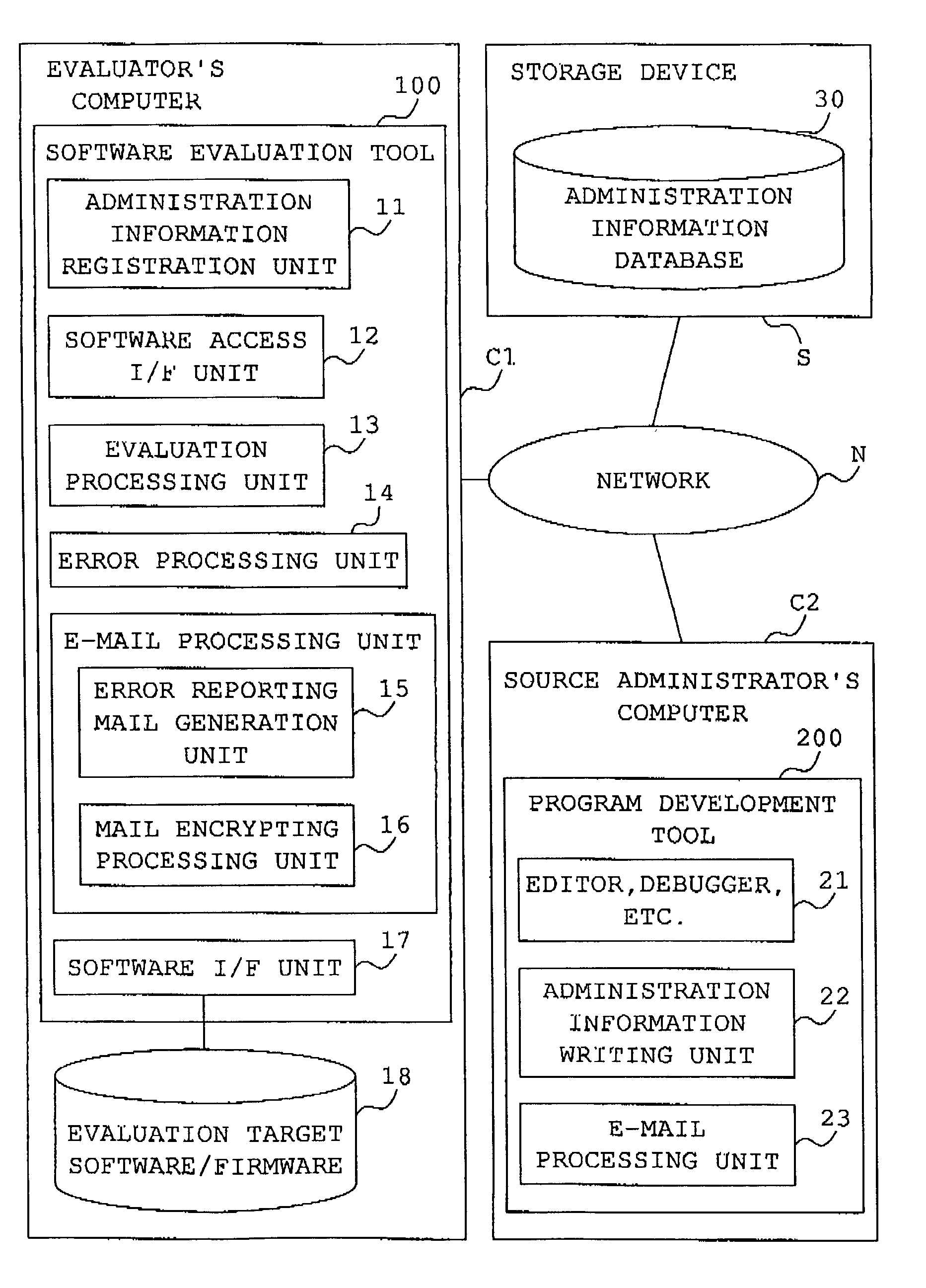
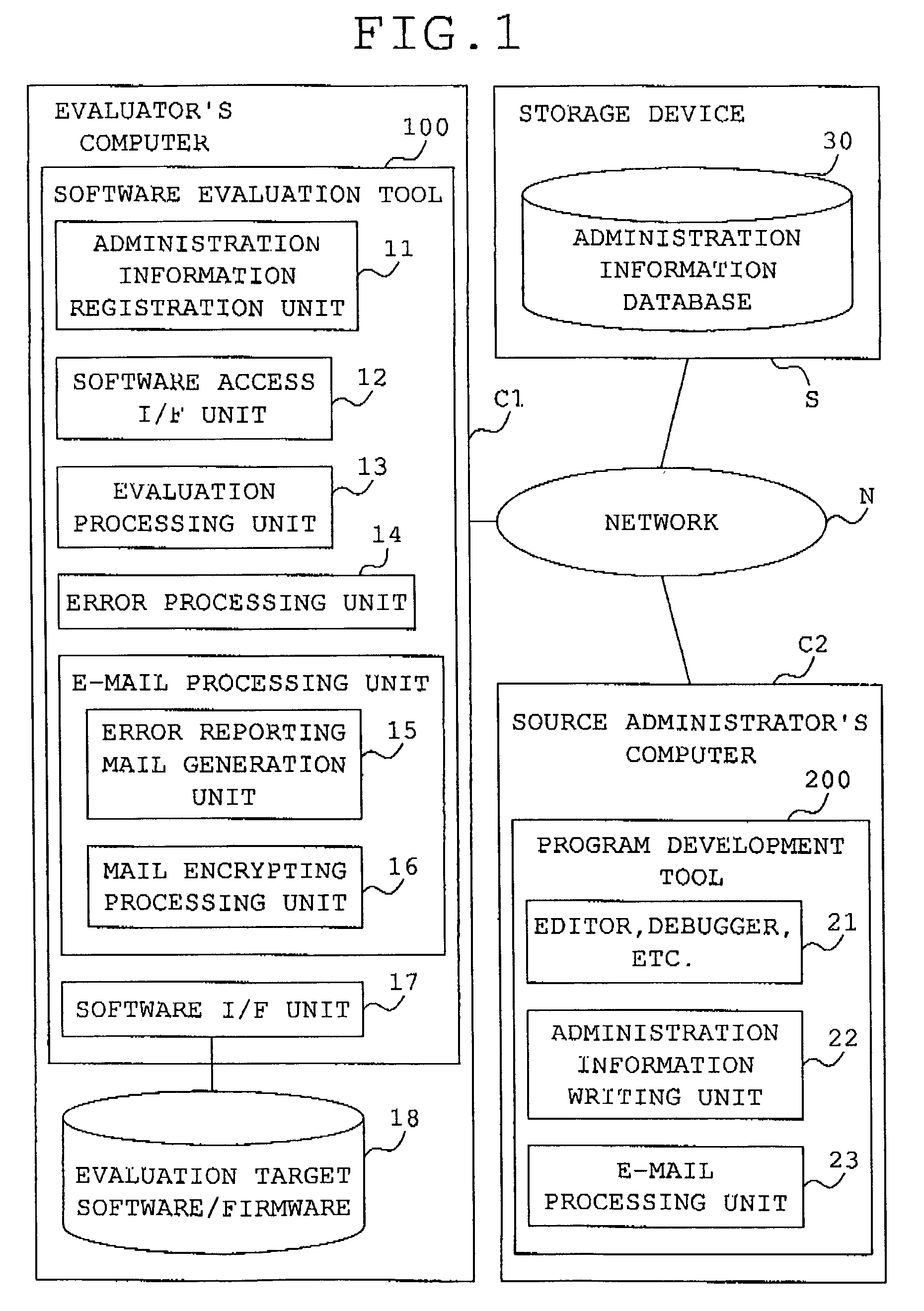
[0057]FIG. 1 is a block diagram showing a structure of a software evaluation system according to the embodiment of the present invention.

[0058]This software evaluation system is used by a group engaged in development of software or firmware.

[0059]This software evaluation system comprises an evaluator's computer C1, a source administrator's computer C2, and a storage device S. The evaluator's computer C1, the source administrator's computer C2, and the storage device S are connected to one another through a network N constituted by a LAN (Local Area Network), the Internet, or the like.

[0060]The evaluator's computer C1 may be such a terminal computer as used by an evaluator who is in charge of processes for evaluating target software or firmware to be developed. The evaluator's computer C1 comprises a processor constituted by a CPU (Central Processing Unit) or the l...


PUM


Abstract

A database stores as administration information of a program, source code identification information for identifying a source code representing the program, function unit identification information for identifying function units of the program which are defined by the source code, and an address of an administrator of the source code. An evaluation computer performs an evaluation process on a program to be evaluated to determine whether the program includes any error command or module, and when determining that the program includes an error command or module, obtains administration information of the program to be evaluated from the database and externally sends source code identification information and function unit identification information included in the obtained administration information to an address included in the obtained administration information.

Description

BACKGROUND OF THE INVENTION[0001]1. Field of the Invention[0002]The present invention relates to a software evaluation system and a software evaluation apparatus. Particularly, the present invention relates to a software evaluation system and a software evaluation apparatus for evaluating or debugging program components such as basic modulus and commands, in development of application software or firmware for devices.[0003]2. Description of the Related Art[0004]In development of software or firmware, if software or firmware is evaluated only by the programmer who has actually coded the software or firmware, objective evaluation of the software or firmware cannot be achieved.[0005]Thus, software evaluation by a third party is required. In this case, the evaluator and the programmer evaluate the software from their respective viewpoints. The programmer tends to consume time in chucking the source codes of modules and commands created by him / herself. On the other hand, the evaluator is...

Claims


Application Information

Patent Timeline
IPC IPC(8): G06F9/44G06F11/30G06F11/28G06F11/36G06F13/00H02H3/05H04K1/00
CPCG06F11/3604G06F11/3664
Inventor MAKIYAMA, FUMIHIRO
Owner NEC CORP
Learn More