
Method for determining temporal and amplitude threshold values of gates during ultrasound testing of spot welding joints

Active Publication Date: 2007-05-01
AGFA NDT
View PDF13 Cites 3 Cited by
  • Summary
  • Abstract
  • Description
  • Claims
  • Application Information

AI Technical Summary

Benefits of technology

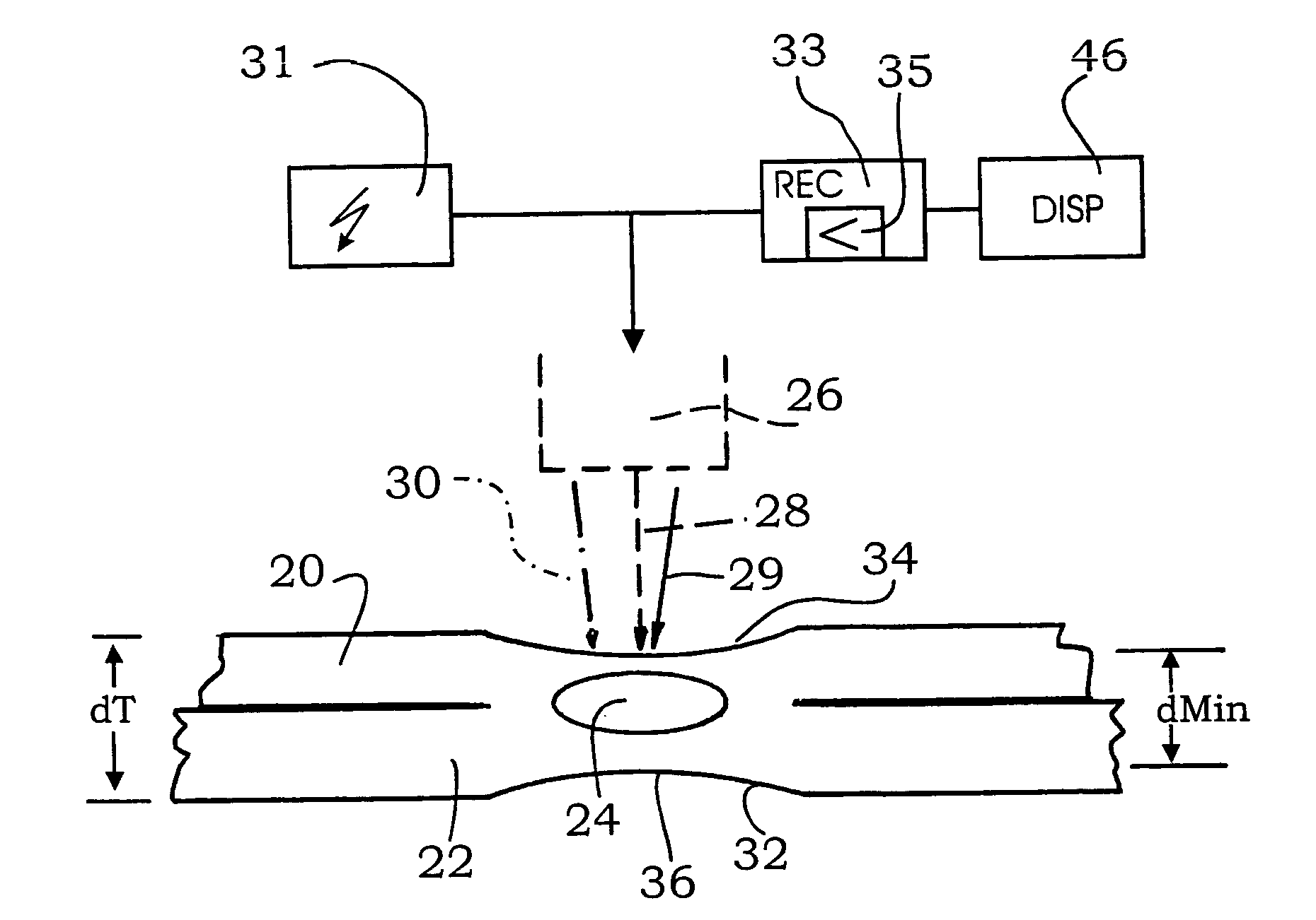
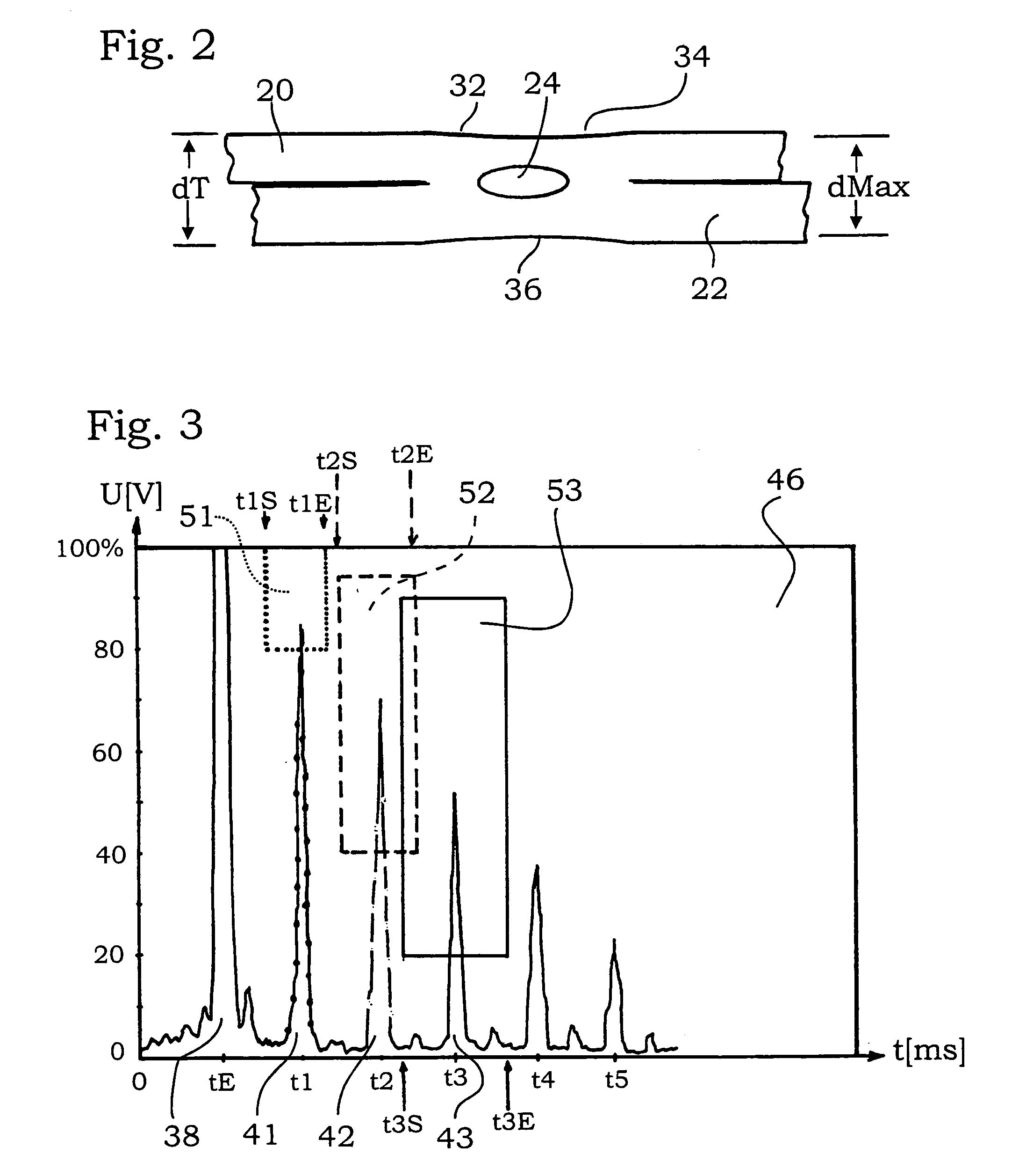
[0027]In a particularly preferred embodiment, the gate for an nth rear wall echo and the associated signals of the nth rear wall echo are represented graphically on the monitor in another manner than the other rear wall echoes e.g., in a dashed line, a dotted line, a dash-dot line and so on. This allows for good association during manual testing.

Problems solved by technology

Optimum coupling is aimed at but must not necessarily be achieved, though.

Method used


Image

  • Method for determining temporal and amplitude threshold values of gates during ultrasound testing of spot welding joints
  • Method for determining temporal and amplitude threshold values of gates during ultrasound testing of spot welding joints
  • Method for determining temporal and amplitude threshold values of gates during ultrasound testing of spot welding joints

Examples


Embodiment Construction

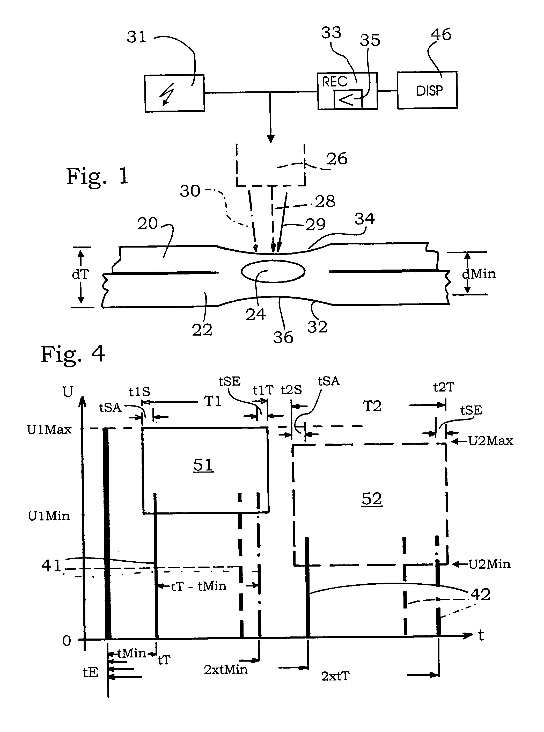
[0033]The FIGS. 1 and 2 each show two metal sheets 20, 22, that are joined together by a spot welding joint. This joint is shown symbolically by a welding spot 24. Usually, the metal sheets 20, 22 have a thickness in the mm range, for example between 0.6 and 1.2 mm. A typical application is in the automotive industry. The spot welding joints have each been made, at least as far as practicable, under the same conditions, namely with comparable or identical metal sheets 20, 22, comparable welding processes, and so on. The welding joints constitute a selected type.

[0034]If another type of spot welding joints is to be tested, for example other sheet thicknesses and so on, it is possible to use the same process as described herein after but it is generally necessary to set other gate values and so on.

[0035]The exemplary embodiments show the connection between two metal sheets 20, 22 although more than two sheets may be joined together. The overall thickness of the sheets joined together ...


PUM


Abstract

The invention relates to a method for determining the threshold value of screens which enable an evaluation of a sound coupling during the ultrasound testing of a series of spot welding joints of a selected type. Initially, a geometrical minimal thickness dMin is established for the spot welding joints. At least one echo of the front surface (entrance echo) is received in addition to one echo of the first reflection on a rear wall of the spot welding joint (first rear wall echo) and at least one further (n-th) rear wall echo. The propagation time tMin of the ultra sound pulse is defined for the path to the front surface to the rear wall and back to the front surface at a minimal thickness dMin and a propagation time tT for the total thickness. A first screen (B1) is set for the signal of the rear wall echo, starting at a moment in time t1S=tE+tMin−tSA and ending at a moment in time t1T=tE+tT+tSE, whereby tSA and tSE are additional small security measures. An n-th screen is correspondingly determined for the n-th rear wall echo. The testing head is oriented differently.

Description

BACKGROUND OF THE INVENTION[0001]The invention generally relates to a method for ultrasound testing of a series of spot welding joints of a selected type and is directed to improvement within such type testing methods, namely to determining threshold values for gates which permit to evaluate the quality of a sound coupling. The invention is primarily concerned with determining temporal threshold values and also proposes amplitude threshold values.[0002]Methods for ultrasound testing of spot welding joints are well known, the reader being referred in this context to U.S. Pat. Nos. 4,208,917; 4,265,119 and 5,537,875.[0003]The known methods may be divided into methods in which ultrasound testing is performed substantially concurrently with the making of the spot welding joints and into such methods by which an already made spot welding joint is tested subsequently by means of ultrasound. The invention only relates to the second type of method, meaning to subsequent testing.[0004]The ul...

Claims


Application Information

Patent Timeline
IPC IPC(8): G01N29/30G01N29/28G01N29/38G01N29/07G01N29/11G01N29/44G01N29/48
CPCG01N29/07G01N29/11G01N29/4445G01N29/48G01N2291/044G01N2291/2632G01N2291/2672
Inventor BUSCHKE, PAULKIRCHNER, BERND
Owner AGFA NDT
Learn More