Apparatus for controlling a tool having a mandrel that must be stroked into or out of a well

a technology of mandrel and tool, which is applied in the direction of drilling casings, wellbore/well accessories, drilling pipes, etc., can solve the problems of abrasive fluid entering the well, corroding and abrasive fluids, and the well may be under very high pressur

Active Publication Date: 2007-05-01
OIL STATES ENERGY SERVICES +1
View PDF25 Cites 34 Cited by
  • Summary
  • Abstract
  • Description
  • Claims
  • Application Information

AI Technical Summary

Benefits of technology

[0021]In accordance with yet another aspect of the invention, a second apparatus for controlling vertical movement of a tubular within a high-pressure well is provided. The second apparatus includes an anchor spool that has a bottom flange for secure, fluid-tight connection atop the high-pressure well, and provides a sealed passageway through which the tubular can be vertically displaced. A tool support ...

Problems solved by technology

The fluids are generally corrosive and abrasive because they are frequently laden with corrosive acids and abrasive propants such as sharp sand.
Wellheads are not designed to accommodate delivery of high-pressure, abrasive fluids into the well.
In any event, once stimulated, the well may be under very high-pressure.
Consequently, situations exist in which the insertion of mandrels used to safely conduct high-pressure fluid through BOPs and other wellhead components or the removal of such mandrels from the wellhead requires mechanical control that cannot be provided by a service rig or a boom truck.
As is well understood in the art, kill fluids are expensive and killing the well may reverse all or part of the beneficial effects of the stimulation process.
As will be evident to those skilled in the art, there is little space available for connecting a single high-pressure stimulation fluid supply line (i.e. a “frac” line) to a high-pressure valve that controls fluid passage through the mandrel, as the cylinders obstruct a substantial portion of a top end of the mandrel, where the high-pressure valve is located.
This limited access becomes increasingly problematic when a rig is used para...

Method used


Image

  • Apparatus for controlling a tool having a mandrel that must be stroked into or out of a well
  • Apparatus for controlling a tool having a mandrel that must be stroked into or out of a well
  • Apparatus for controlling a tool having a mandrel that must be stroked into or out of a well

Examples


Embodiment Construction

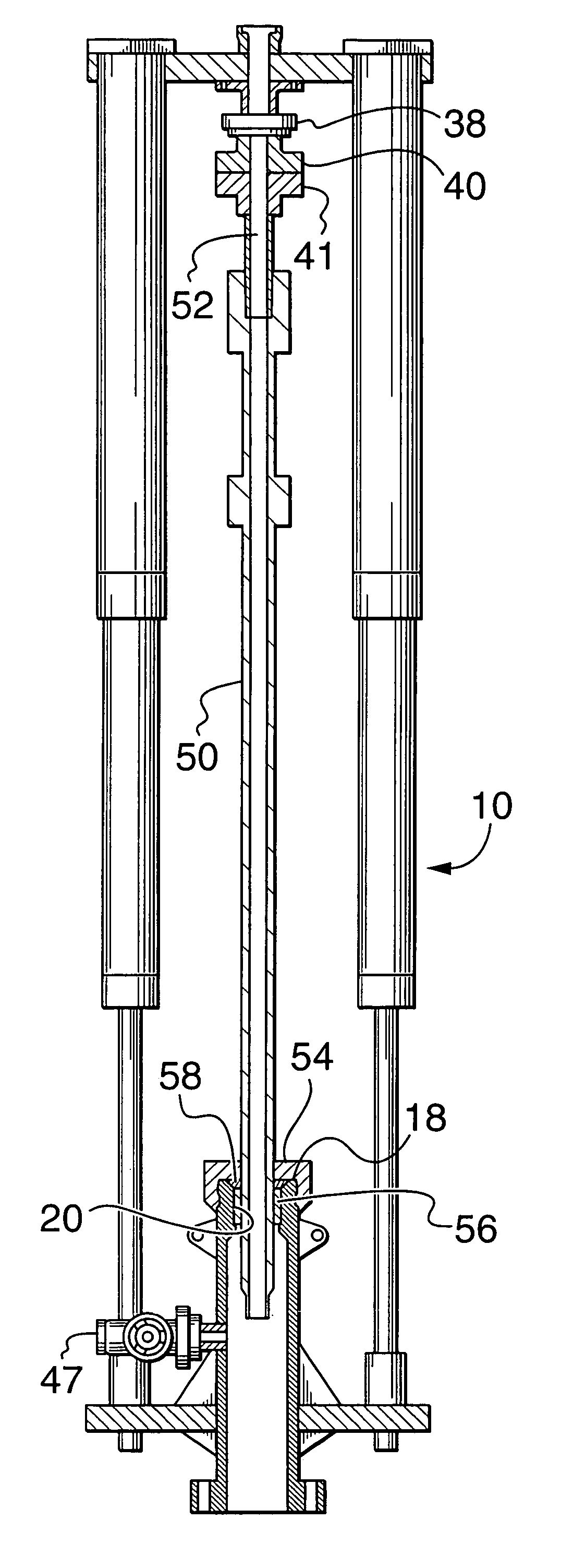
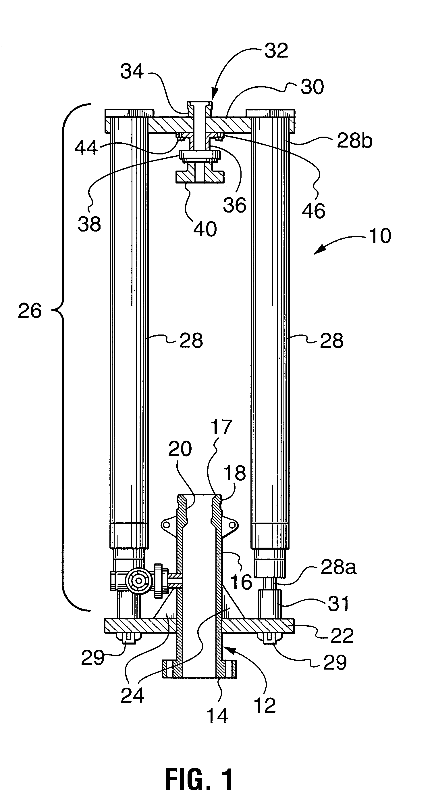
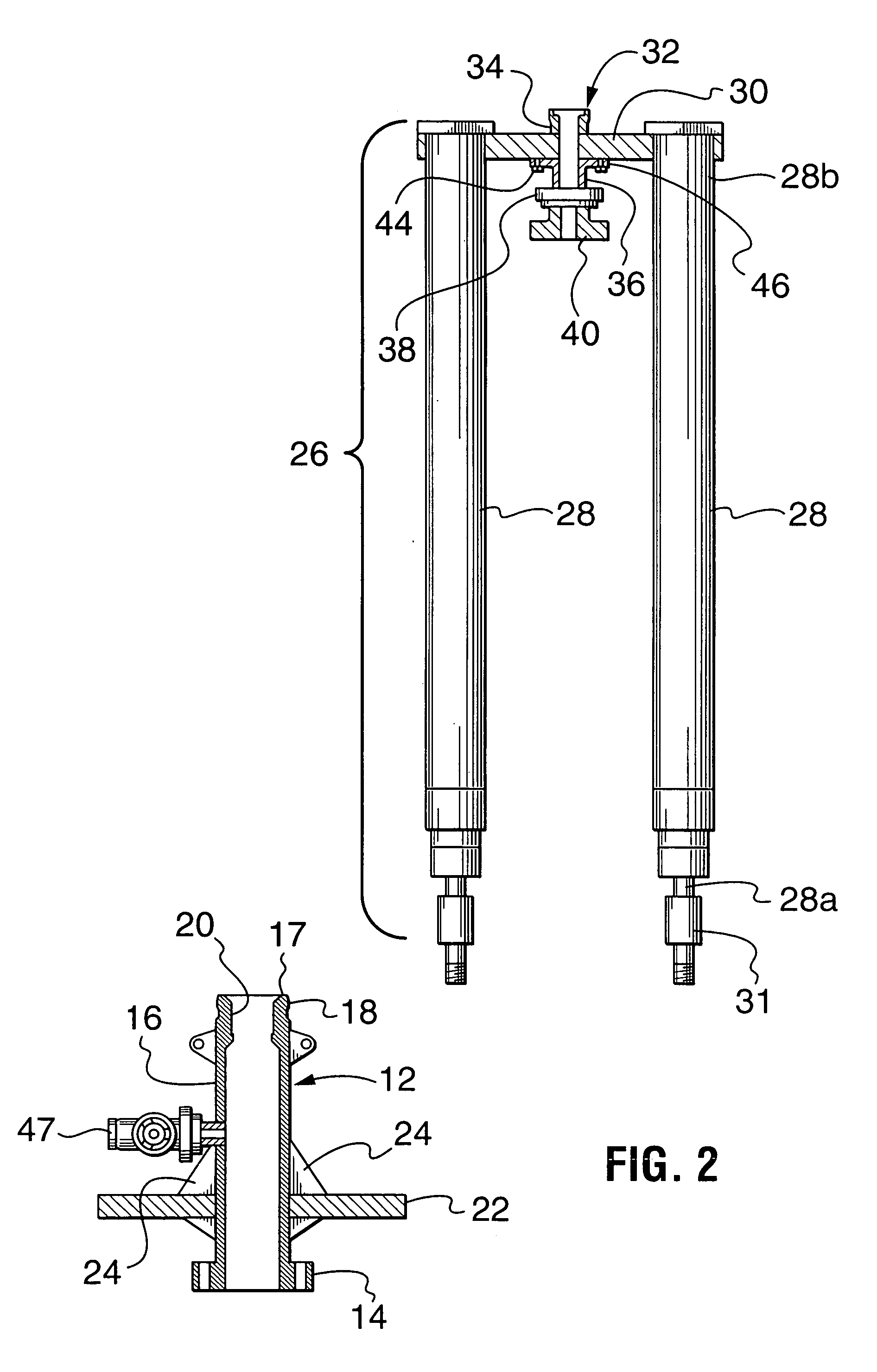
[0029]The invention provides an apparatus for controlling vertical movement of a tubular that is designed to be inserted into a high-pressure well. The apparatus includes an anchor spool, a tool support structure above the anchor spool, and a plurality of symmetrically disposed piston cylinders interconnecting the two. The tubular may be a landing joint or a high-pressure mandrel of either a well stimulation tool, or a wellhead isolation tool. The apparatus therefore has multiple uses. The apparatus further provides unobstructed access to a top end of the tubular because the piston cylinders are connected to a bottom side of the tool support structure. The piston cylinders are radially distributed to provide a balanced control force to permit installation of a well stimulation tool, or a wellhead isolation tool connected to the tool support structure.

[0030]FIG. 1 is a schematic side-elevational view of the apparatus 10 in accordance with an embodiment of the invention. The apparatus...


PUM


Abstract

An apparatus for controlling vertical movement of a tubular within a wellhead includes an anchor spool connected atop the wellhead, and a detachable superstructure supporting the tubular. The anchor spool provides connectors for detachably connecting bottom ends of at least two piston cylinders of the detachable superstructure. The tubular may be a landing joint or a high-pressure mandrel of either a well stimulation tool, or a well isolation tool. The apparatus provides unobstructed access to a top end of the tubular. The anchor spool includes an elongated sidewall and an axial passage through which a tubing hanger can be reciprocated. The height of the sidewall permits the apparatus to be used for landing/removing a tubing string even if the anchor spool is mounted directly to a blowout preventer (BOP).

Description

CROSS-REFERENCE TO RELATED APPLICATIONS[0001]Not Applicable.MICROFICHE APPENDIX[0002]Not Applicable.TECHNICAL FIELD[0003]The present invention relates to equipment for servicing oil and gas wells and, in particular, to an apparatus for controlling a tool having a mandrel or other tubular that must be stroked into or out of a high-pressure well.BACKGROUND OF THE INVENTION[0004]Most oil and gas wells eventually require some form of stimulation to enhance hydrocarbon flow in order to make or keep them economically viable. The servicing of oil and gas wells to stimulate production requires the pumping of fluids under high-pressure. The fluids are generally corrosive and abrasive because they are frequently laden with corrosive acids and abrasive propants such as sharp sand.[0005]Wellheads are not designed to accommodate delivery of high-pressure, abrasive fluids into the well. Consequently, isolation tools in various forms and configurations have been invented to protect wellheads durin...

Claims


Application Information

Patent Timeline
IPC IPC(8): E21B33/03E21B33/068
CPCE21B33/068
Inventor DALLAS, L. MURRAY
Owner OIL STATES ENERGY SERVICES
Why Eureka
Try Eureka