Belt assembly

a belt and assembly technology, applied in the field of belt assemblies, can solve the problems that the belt assembly of the previous generation, which is not suitable for land and air vehicles, cannot meet the demands of the present generation, and achieves the effects of facilitating the attachment of the belt assembly, preventing heat accumulation, and facilitating the extraction of the occupant from the vehicl

Inactive Publication Date: 2007-05-01
SCHROTH SAFETY PRODS
View PDF20 Cites 36 Cited by
  • Summary
  • Abstract
  • Description
  • Claims
  • Application Information

AI Technical Summary

Benefits of technology

[0013]The two body belts of the belt assembly according to the invention extend from the area of the central buckle across the torso, shoulders and back of the occupant. The body belts can be constructed length-adjustable, whereby the length change can be realized e.g. through division in length portions, preferably in the area of the torso. Attachment of the body belts can be implemented preferably in the area of the locking tongues, regardless whether they are directly associated to the lap belts or whether the locking tongues include receptacles for engagement tongues provided on the lap belts. As the body belts are guided crosswise at the back of the occupant and interconnected, e.g. sewed, at the crossing points. This measure results in improved load conduction.
[0025]According to another feature of the present invention, the vest has a back region which may be provided with an elastic portion. Such an elastic portion is intended to facilitate the adjustment to the sitting position, on one hand, and to the standing position, on the other hand.

Problems solved by technology

Various belt assemblies heretofore designed for land and air vehicles are not suitable to meet these demands as they normally take into account only one or the other position of an occupant, however ignore the fact that the occupant must be restrained during activity while sitting or standing.

Method used


Image

  • Belt assembly
  • Belt assembly
  • Belt assembly

Examples


Embodiment Construction

[0034]Throughout all the Figures, same or corresponding elements are generally indicated by same reference numerals. These depicted embodiments are to be understood as illustrative of the invention and not as limiting in any way. It should also be understood that the drawings are not necessarily to scale and that the embodiments are sometimes illustrated by graphic symbols, phantom lines, diagrammatic representations and fragmentary views. In certain instances, details which are not necessary for an understanding of the present invention or which render other details difficult to perceive may have been omitted.

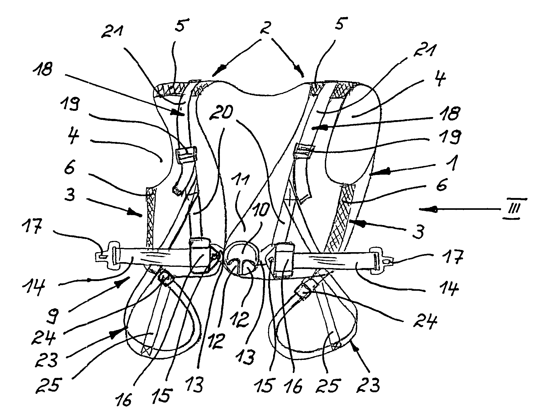
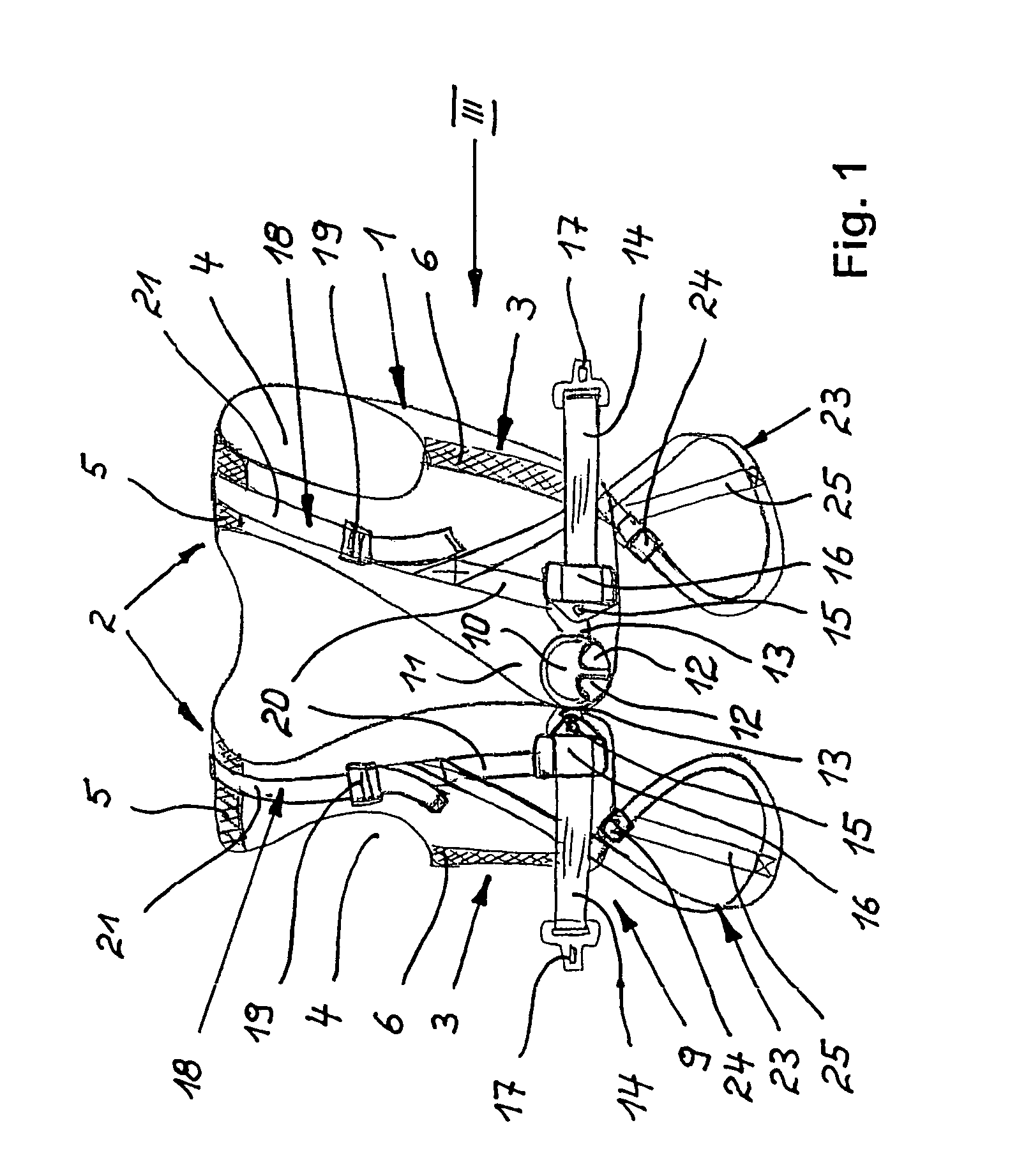
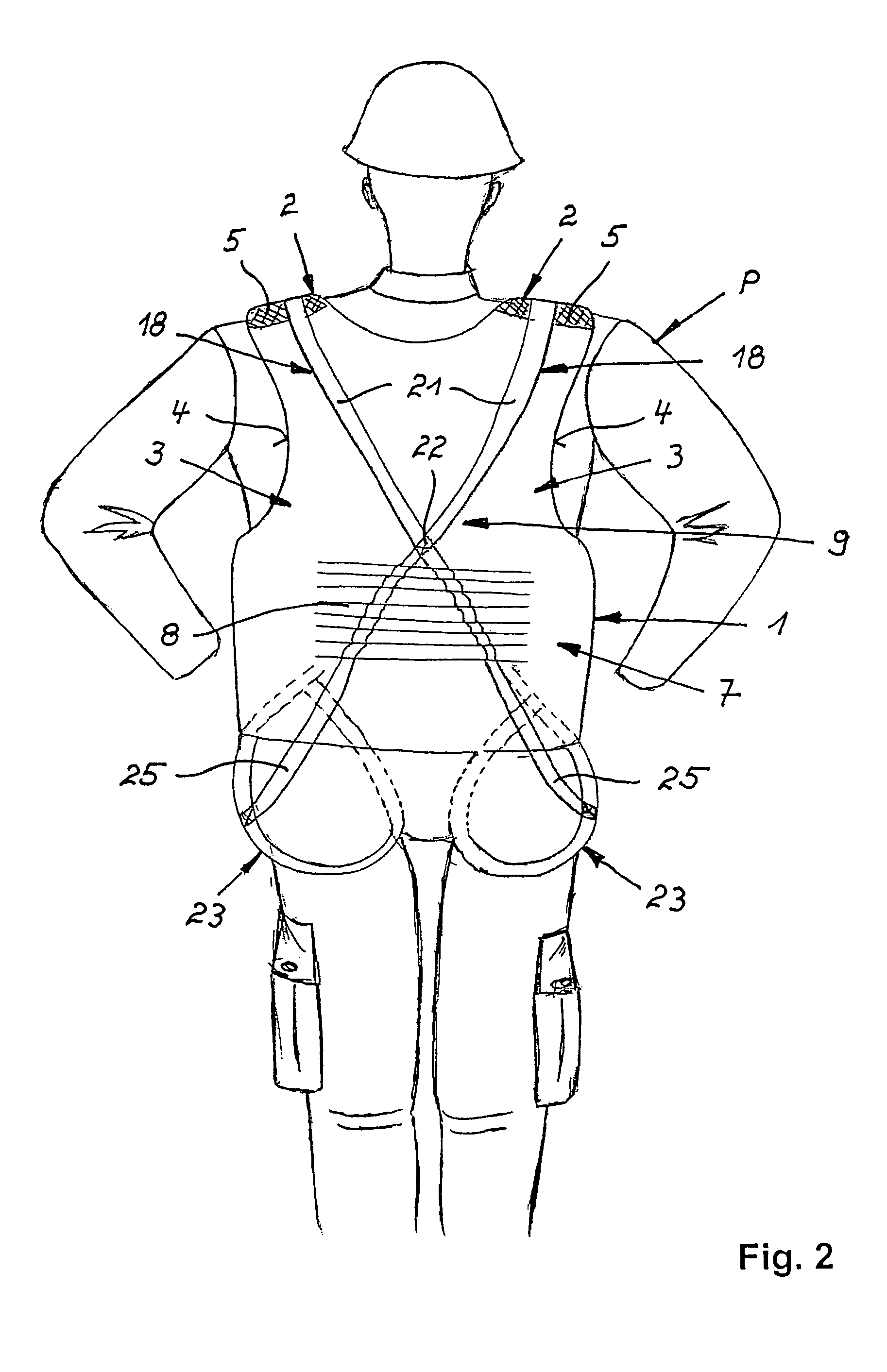
[0035]Turning now to the drawing, and in particular to FIG. 1, there is shown a front perspective view of a belt assembly, generally designated by reference numeral 9. In the non-limiting example of FIG. 1, the belt assembly is connected to a vest, generally designated by reference numeral 1 and worn by an occupant P of a vehicle F (indicated in FIGS. 5 to 7), when the occupan...


PUM


Abstract

A belt assembly for securing the sitting and standing positions of an occupant of a vehicle has two lap belts which can be coupled to the vehicle and are brought together at an abdomen-side central buckle and which are swingable in parallel relation to the occupant's body and include retractors. Two length-adjustable body belts extend from the central lock across the torso, shoulders and back of the occupant, and two length-adjustable, loop-like leg belts are connected to length portions of the body belts, with the length portions at least indirectly connected to the lap belts. The body belts have buckle-distal ends which are fastened to the leg belts. The body belts cross at the back of the occupant and are connected there with one another. The belt assembly can be directly connected to a vest which can be suited to the body of the occupant via hook-and-loop fasteners.

Description

CROSS-REFERENCES TO RELATED APPLICATIONS[0001]This application claims the benefit of prior filed U.S. provisional Application No. 60 / 503,755, filed Sep. 18, 2003, pursuant to 35 U.S.C. 119(e), the disclosure of which is incorporated herein by reference.BACKGROUND OF THE INVENTION[0002]The present invention relates, in general, to a belt assembly for securing an occupant of a vehicle, such as, e.g., the position of the commander of a military armored vehicle, in a sitting position as well as standing position.[0003]The commander of an armored vehicle can assume a standing position, when the hatch is open, for surveying the surroundings. On the other hand, the commander assumes a sitting position, when the hatch is closed. The commander is able to completely fulfill his jobs in both positions only when restrained in these positions also during travel in rough terrain, when hitting an obstacle, at mine explosions, or at rollover of an armored vehicle. Also rescue personnel and physicia...

Claims


Application Information

Patent Timeline
Patent Type & Authority Patents(United States)
IPC IPC(8): B60R22/00B60R22/14B60R21/00
CPCB60R22/14B60R2021/0032B60R2021/0037
Inventor SCHROTH, CARL-JURGEN
Owner SCHROTH SAFETY PRODS
Why Eureka
Try Eureka