Method, system and device for delivering phototherapy to a patient

a technology for delivering phototherapy and patients, applied in the direction of therapy, lighting support devices, lighting and heating apparatus, etc., can solve the problems of reducing the light producing capacity of light sources, the surface mount of leds with respect to the substrate, and the inability to ensure the user's us

Active Publication Date: 2007-05-01
BENCH WALK LIGHTING LLC
View PDF7 Cites 61 Cited by
  • Summary
  • Abstract
  • Description
  • Claims
  • Application Information

AI Technical Summary

Problems solved by technology

However, one problem associated with LED illumination array in a phototherapy context is the surface mount of the LED with respect to the substrate.
Additionally, in the surface mount configuration, the dissipation of heat from the light source can be extremely difficult thereby resulting in a decrease in the light producing capabilities of the light source to ensure that a user is not burned.

Method used


Image

  • Method, system and device for delivering phototherapy to a patient
  • Method, system and device for delivering phototherapy to a patient
  • Method, system and device for delivering phototherapy to a patient

Examples


Embodiment Construction

[0022]The present invention provides a reverse mounted flexible light array having a variety of applications, such as for the treatment of hyperbilirubinemia in neonates, and psoriasis, seasonal affective disorder, sleep disorders, herpes, acne, skin cancer, and other medical conditions. The invention is an advance over current fiber-optic type illumination panels because of the increased intensity of the light-generating sources. Various configurations are described herein, none of which should be construed as particularly preferred in general.

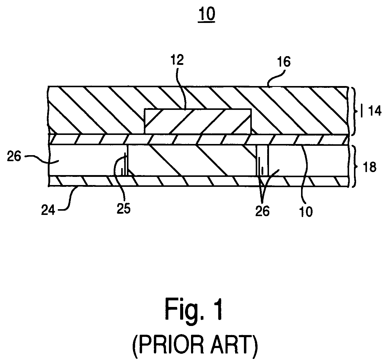
[0023]With reference now to FIG. 2, in one embodiment, an illumination panel 200 of the present invention having an elongate, planar, flexible body 232 is shown having a front or contact surface 234 and a back surface facing the opposite direction and not seen in FIG. 2. In the embodiment, the illumination panel 200 has a rounded rectangular configuration with a length L, a width W, and a thickness T, with the length L being substantially gre...


PUM


Abstract

A system and method for a reverse mounted light array. In one method embodiment, the present invention couples a reverse mounted light-generating source with a substrate. Additionally, the present invention couples an electrical portion of the reverse mounted light generating source with a conductive trace coupled to the reverse side of the substrate, wherein the coupling of the conductive trace with the substrate and the reverse mounted light generating source forms a reverse mounted light array.

Description

FIELD OF INVENTION[0001]Various embodiments of the present invention relate to the field of light emission devices in an array.BACKGROUND OF THE INVENTION[0002]Light emitting diodes (LEDs) are devices that use a semiconductor diode that emits light when charged with electricity. LEDs provide light in a wide array of electronic devices. For example, LEDs are used as on / off indicators in electronic devices, are used to provide LCD or keypad backlighting in handheld devices, such as personal digital assistants (PDAs) and cellular telephones, and are used for digital display readouts, such as electronic signs. Typically, LEDs are manufactured into an electronic chip (e.g., LED chips) that provide for easy integration into electronic devices.[0003]Moreover, LEDs have found their way into lighting applications, photo-therapeutic applications, and other applications where a compact, low voltage, rugged, and high efficiency light source is advantageous. In many such applications, a number o...

Claims


Application Information

Patent Timeline
Patent Type & Authority Patents(United States)
IPC IPC(8): F21V21/00A61N5/00A61N5/06F21K99/00F21V29/00H05K1/02H05K1/18
CPCA61N5/0613F21K9/00A61N2005/005A61N2005/0645A61N2005/0652H05K1/0203H05K1/182H01L2224/48091H01L2924/00014
Inventor LEE, KIAN SHINCHUA, JANET BEE YINKUAN, YEW CHEONGCHENG, HENG YOWNG, KEE YEANOU, WEN YA
Owner BENCH WALK LIGHTING LLC
Why Eureka
Try Eureka