Electroluminescent light therapy devices

a technology of light therapy and electroluminescent light, which is applied in the field of light therapy, can solve the problems of user discomfort, user inability to receive such light therapy, and even temporarily blindness,

Inactive Publication Date: 2005-12-15
LIVE WIRE ENTERPRISES
View PDF7 Cites 97 Cited by
  • Summary
  • Abstract
  • Description
  • Claims
  • Application Information

AI Technical Summary

Benefits of technology

[0010] Wearable devices including a hat or cap, eyeglasses, an eye mask, or a face mask deliver light from light-emitting diodes or deliver electroluminescent light from a light source including an electroluminescent wire or flat panel powered by an inverter connected to the hat or cap, the eyeglasses, the eye mask, or the face mask. The delivery of the light is for entertainment or therapeutic purposes. Delivery of therapeutic light to the retinal area or to the skin of the user by a wearable device, without the use of the hands of the user, applies consistent levels of the therapeutic light to relax the user, to remove wrinkles in the skin, and to impart other healing effects. A sufficient amount of lux at appropriate optical wavelengths is generated to be incident for long periods upon the retina of the user or upon the skin of the user for healing effect.
[0012] A therapeutic device applies therapeutic light to a portion of the face of the user, with the therapeutic device having a light source for emitting the therapeutic light; and a wearable member worn by the user and having the light source mounted thereon for positioning the light source substantially adjacent to the portion of the face of the user, thereby causing healing effects in the portion of the face. The portion of the face may be the retina of an eye of the user, or may be a portion of the skin of the face of the user, such as an area of skin substantially surrounding the eyes of the user, or substantially the entire face of the user.
[0015] A kit for light therapy may also be included, with the kit having a wearable device wearable by a user and having a wearable member and a light source for emitting therapeutic light, with the light source mounted on the wearable member for positioning the light source substantially adjacent to the portion of the face of the user, thereby causing healing effects in the portion of the face; and a power source wearable by a user and electrically connectable to the light source for providing electrical power to the light source, thereby causing the emission of the therapeutic light.

Problems solved by technology

Such light boxes are not portable, so the user cannot receive such light therapy unless the user is stationary.
In addition, the use of light boxes to provide a bright full spectrum of light, such as white light, is painful to the eyes and therefore makes users uncomfortable, and even temporarily blinded.
Therefore, the duration of use must be relatively short, limiting their therapeutic value.
Furthermore, electroluminescent (EL) light sources are not as painful to the eyes, but the delivering the proper amount of lux with known light sources such as EL devices is difficult due to the rapid degradation of inverters used in EL devices of the prior art, and thus the delivery of light to the eyes by EL light sources decreases rapidly.
Accordingly, prior art light therapy devices have short operating lifetimes and so are of limited therapeutic value.
However, the delivery of such illumination is difficult if such light sources are not portable or wearable, such as a light box or a tanning bed which cannot be readily worn or carried about by the user.
In addition, portable devices which are carried require the use of one's hands to continually apply the illumination, thus limiting one's free hands for other activities.
Furthermore, the application of illumination by hand may promote uneven therapy to the user, since one's hand carrying the therapeutic illumination device may not be held in a constant position as one walks or performs other activities, and the user may tire of holding the carried therapeutic illumination device, which may cause the user to cease the therapy.

Method used


Image

  • Electroluminescent light therapy devices
  • Electroluminescent light therapy devices
  • Electroluminescent light therapy devices

Examples


first embodiment

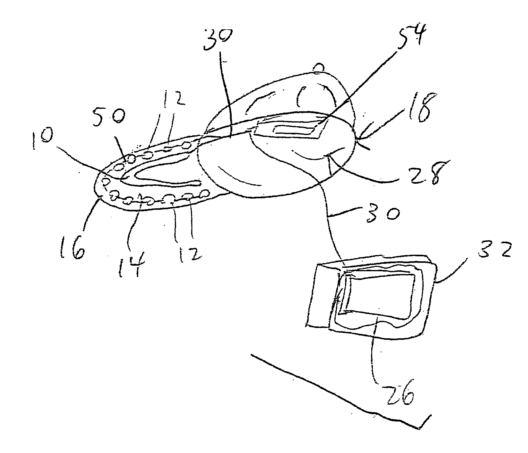
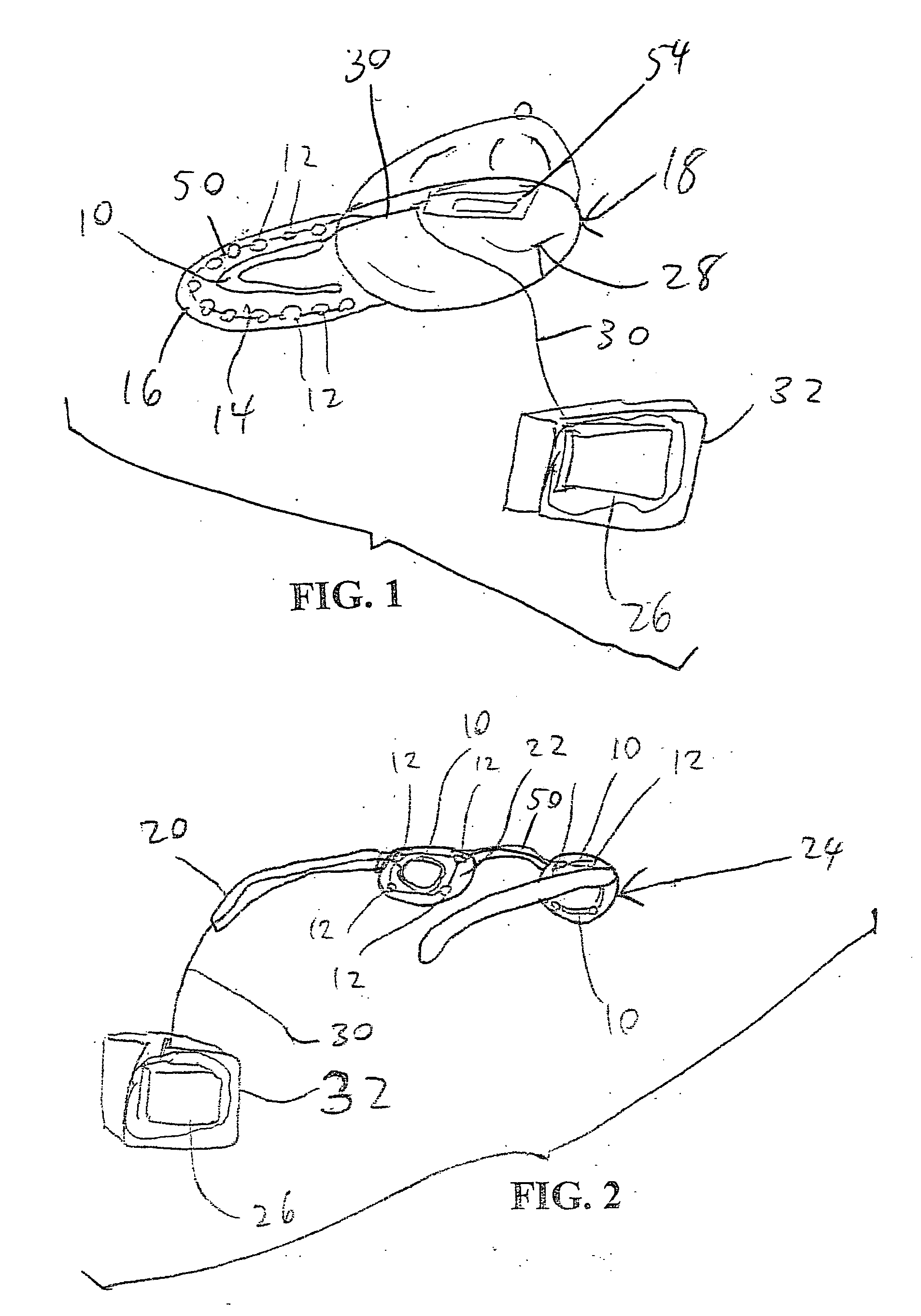
[0035] In the present invention, FIG. 1 is a bottom rear left side perspective view of a cap 18 having a light source composed of an EL light source 10 and LEDs 12 forming an electrical circuit with connecting wires 50 to be connected to lead wires 30 to a power source such as the power source 26 external to the cap 18, which may be a portable and / or removably attachable power pack having the housing 32 with the battery 26 therein; or alternatively a power source 54 internally mounted in the interior 28 of the cap 18.

[0036]FIG. 5 is a top front left side perspective view of a user wearing a cap 18 as in FIG. 1, with a cut-away view showing the EL light source 10, the LEDs 12, and the connecting wires 50 on the underside 14 of the brim 16, and the lead wire 30 extend from the electrical circuit formed by the components 10, 12, 50 out to the housing 32 to the battery 26. In use, the cap 18 is worn by the user, and the housing 32 is removably attached, for example, with a clip, to the ...

second embodiment

[0037] In the present invention, FIG. 2 is a bottom rear right side perspective view of a set of eyeglasses 24 having a light source such as an EL wire 10 and / or LEDs 12. In use, as shown in FIG. 6, which is a top front left side perspective view of a user wearing the set of eyeglasses 24 as in FIG. 2, the frames 20 of the eyeglasses 24 contain or have mounted thereon the EL wires 10 and / or the LEDs 12. In a cut-away view of FIG. 6, the connecting wires 50 are shown extending between the EL wires 10 and / or LEDs 12, for example, over and / or through the bridge of the frames 20, and the lead wire 30 extend from the electrical circuit formed by the components 10, 12, 50 out of or along the ear pieces of the frames 20 to the battery 26. In use, the eyeglasses 24 are worn by the user, and the housing 32 is removably attached, for example, with a clip, to the clothing of the user.

third embodiment

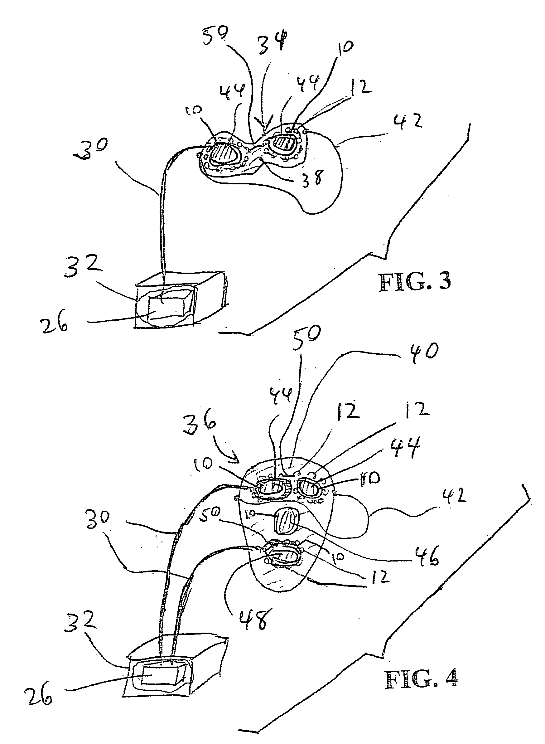
[0038] In the present invention, FIG. 3 is a bottom rear left side perspective view of an eye mask 34 having a light source such as an EL wire 10 and / or LEDs 12 mounted on an eye mask member 38, such as a flexible plastic or cloth piece generally shaped to substantially cover the eyes of the user. In use, as shown in FIGS. 7-8, which are top front left side perspective views of a user wearing the eye mask 34 as in FIG. 3, in a cut-away view, the eye mask member 38 has mounted thereon on the side facing the face of the user the EL wires 10 and / or the LEDs 12. In the cut-away views of FIGS. 7-8, the connecting wires 50 are shown extending between the EL wires 10 and / or LEDs 12, for example, over and / or through the portion of the eye mask member 38 between the eyes of the user, and the lead wire 30 extends from the electrical circuit formed by the components 10, 12, 50 out of the eye mask member 38 to the battery 26. In an alternative embodiment, the lead wire 30 may be connected to or...


PUM


Abstract

Wearable devices including a hat or cap, eyeglasses, an eye mask, or a face mask deliver light from light-emitting diodes or deliver electroluminescent light from a light source including an electroluminescent wire or flat panel powered by an inverter connected to the hat or cap, the eyeglasses, the eye mask, or the face mask. The delivery of the light is for entertainment or therapeutic purposes. Delivery of therapeutic light to the retinal area or to the skin of the user by a wearable device, without the use of the hands of the user, applies consistent levels of the therapeutic light to relax the user, to remove wrinkles in the skin, and to impart other healing effects. A sufficient amount of lux at appropriate optical wavelengths is generated to be incident for long periods upon the retina of the user or upon the skin of the user for healing effect.

Description

CROSS-REFERENCE TO RELATED APPLICATIONS [0001] This application claims priority to U.S. provisional patent application No. 60 / 570,943, filed May 12, 2004, now abandoned, which is incorporated herein by reference in its entirety.BACKGROUND OF THE INVENTION [0002] 1. Field of the Invention [0003] This invention relates to light therapy, and in particular to a device which uses electroluminescent light for light therapy. [0004] 2. Description of the Related Art [0005] Short wavelengths of light in the blue portion of the electromagnetic spectrum, at wavelengths in the range of about 460 nanometers (nm.) to about 480 nanometers at illumination levels in the range of about 2,000 lux to about 30,000 lux, are most effective at affecting the circadian system of a person. A lux is a measure of illumination equal to one lumen per square meter. The color produced by an electroluminescent (EL) light device emitting such wavelengths simulates a clear blue sky. The EL light device may be powered ...

Claims


Application Information

Patent Timeline
Patent Type & Authority Applications(United States)
IPC IPC(8): A61B18/20A61M21/00A61M21/02A61N1/00A61N5/06
CPCA61B18/203A61B2018/00452A61B2018/0047A61M21/02A61M2021/0044A61N2005/0653A61N5/0618A61N2005/0647A61N2005/0648A61N2005/0652A61N5/0616
Inventor FELDMAN, HAROLD
Owner LIVE WIRE ENTERPRISES
Why Eureka
Try Eureka